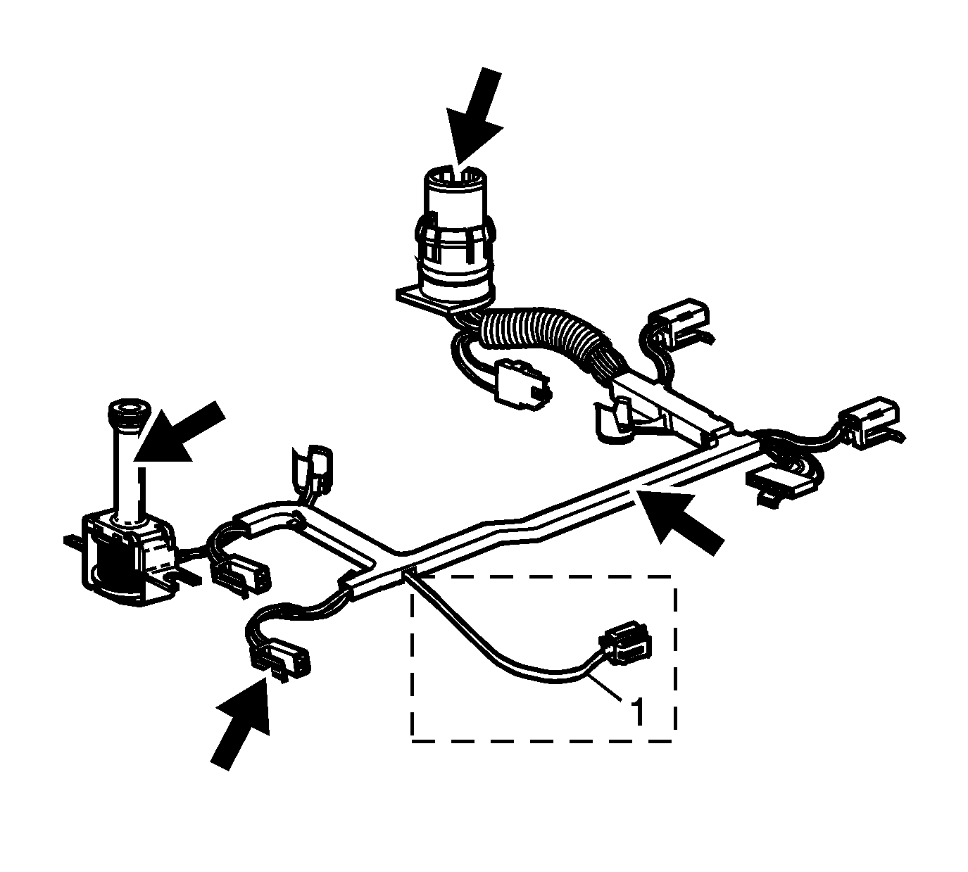
Important: Secondary fluid pump connector (1) is used for M33 models only.
- Inspect the wiring harness and solenoid assembly for the following conditions:
| • | Loose electrical terminals |
| • | Worn, missing, or cut pass-through connector O-ring seal. |
- Install the transmission wiring harness pass-through connector into the transmission case. Ensure connector tabs lock into place.
- Move the harness to one side in order to install the valve body.
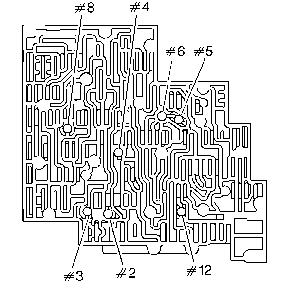
Important: Valve bodies are model dependent.
- Install the checkballs (2-6, 8, 12) in the valve body and retain checkballs with
J 36850
or an equivalent.
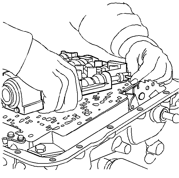
- Install the valve body over the
J 25025-5
Guide Pins, and connect the manual valve link to the manual valve.
- Install two bolts to hold the valve body in place.
- Remove the
J 25025-5
.
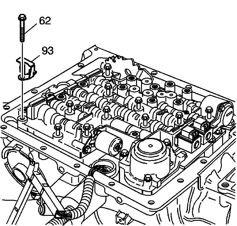
- Install the fluid level indicator stop bracket (93) if equipped and the valve body bolts (62) that are shown only.
- Finger tighten the bolts.
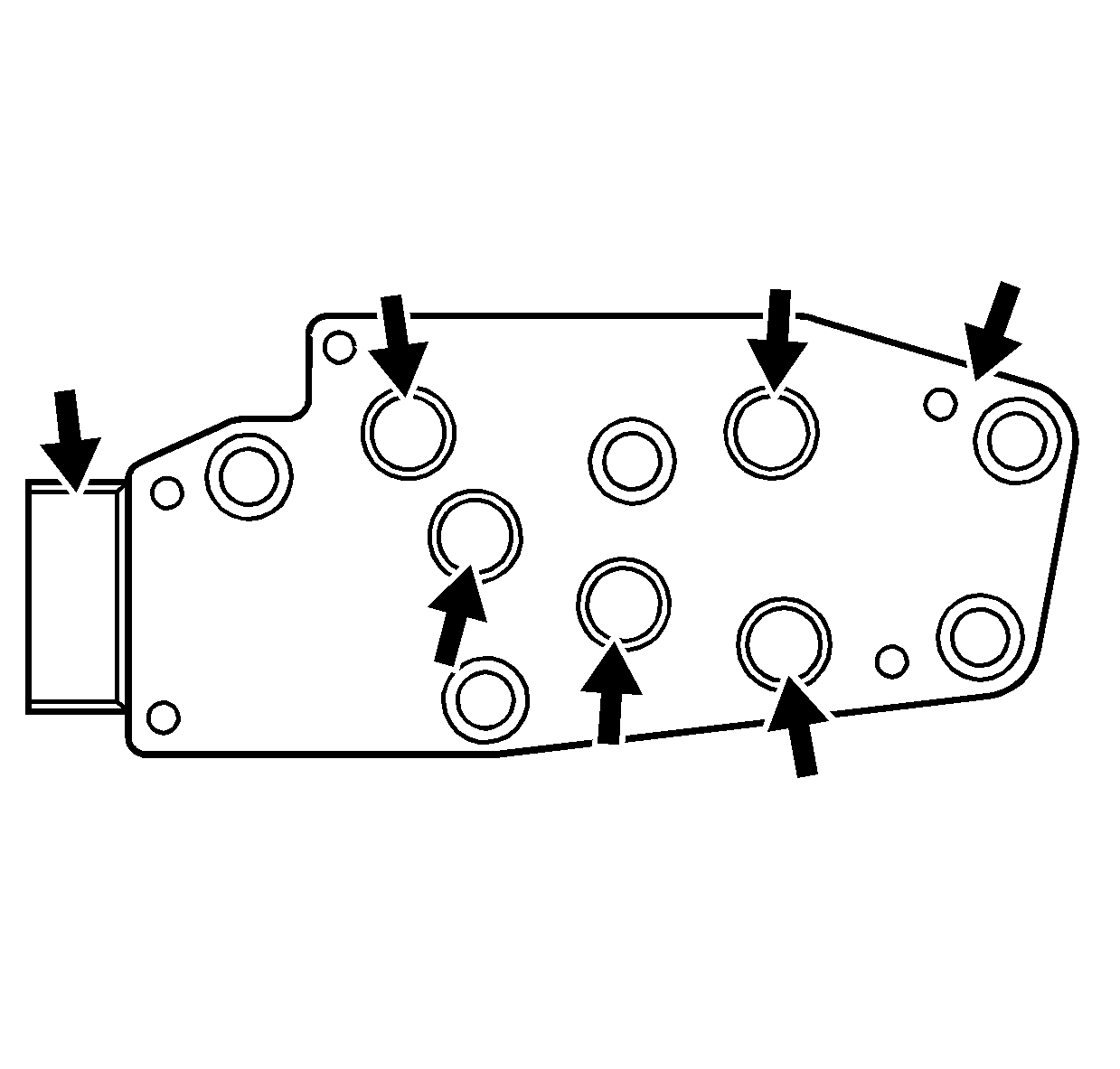
- Inspect the Transmission Fluid Pressure (TFP) Manual Valve Position Switch Assembly for the following conditions:
| • | Damaged or missing O-rings |
| • | Loose electrical terminals |
| • | Poor terminal retention |
| • | Sediment in switch membrane |
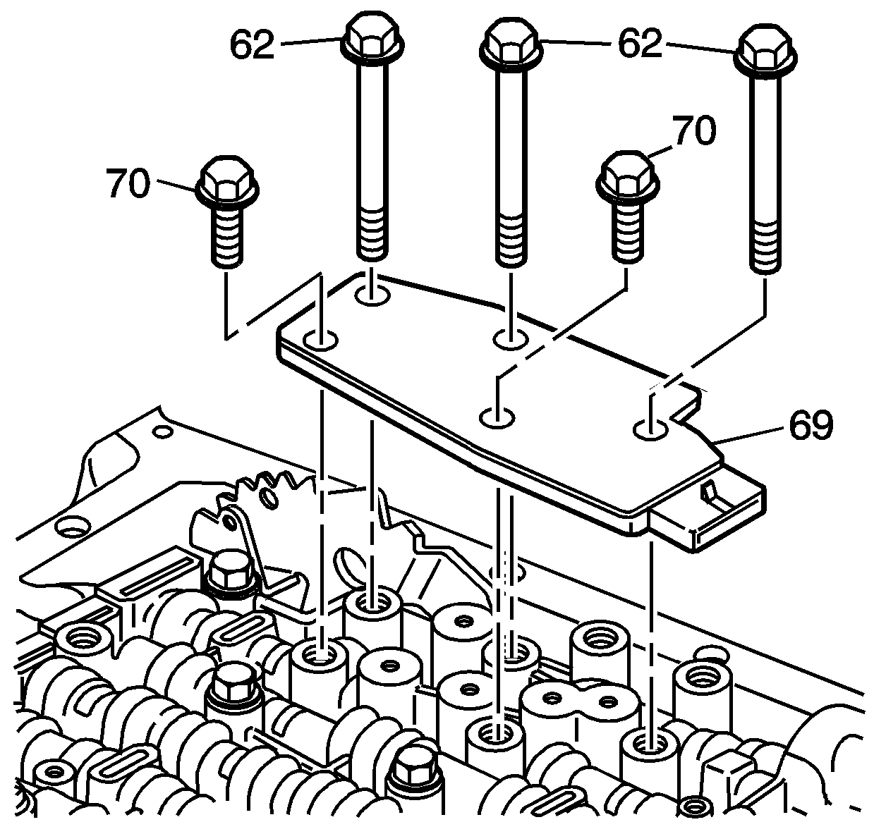
- Install the TFP manual valve position switch (69) and bolts (62, 70).
- Install the transmission wiring harness on the valve body.
Notice: Use the correct fastener in the correct location. Replacement fasteners
must be the correct part number for that application. Fasteners requiring
replacement or fasteners requiring the use of thread locking compound or sealant
are identified in the service procedure. Do not use paints, lubricants, or
corrosion inhibitors on fasteners or fastener joint surfaces unless specified.
These coatings affect fastener torque and joint clamping force and may damage
the fastener. Use the correct tightening sequence and specifications when
installing fasteners in order to avoid damage to parts and systems.
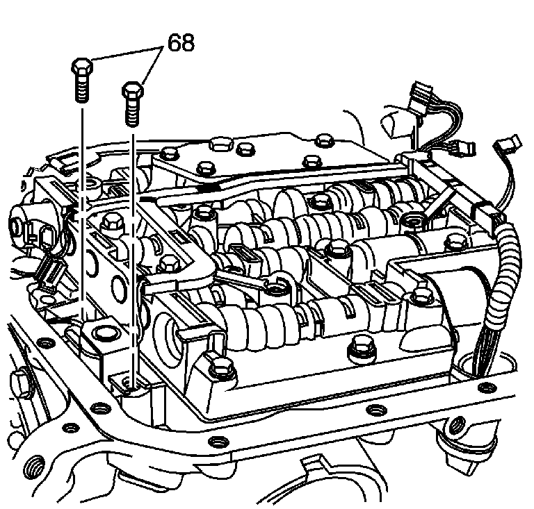
- Install the TCC solenoid valve and bolts (68).
Tighten
Tighten the bolts to 8-14 N·m (6-10 lb ft).
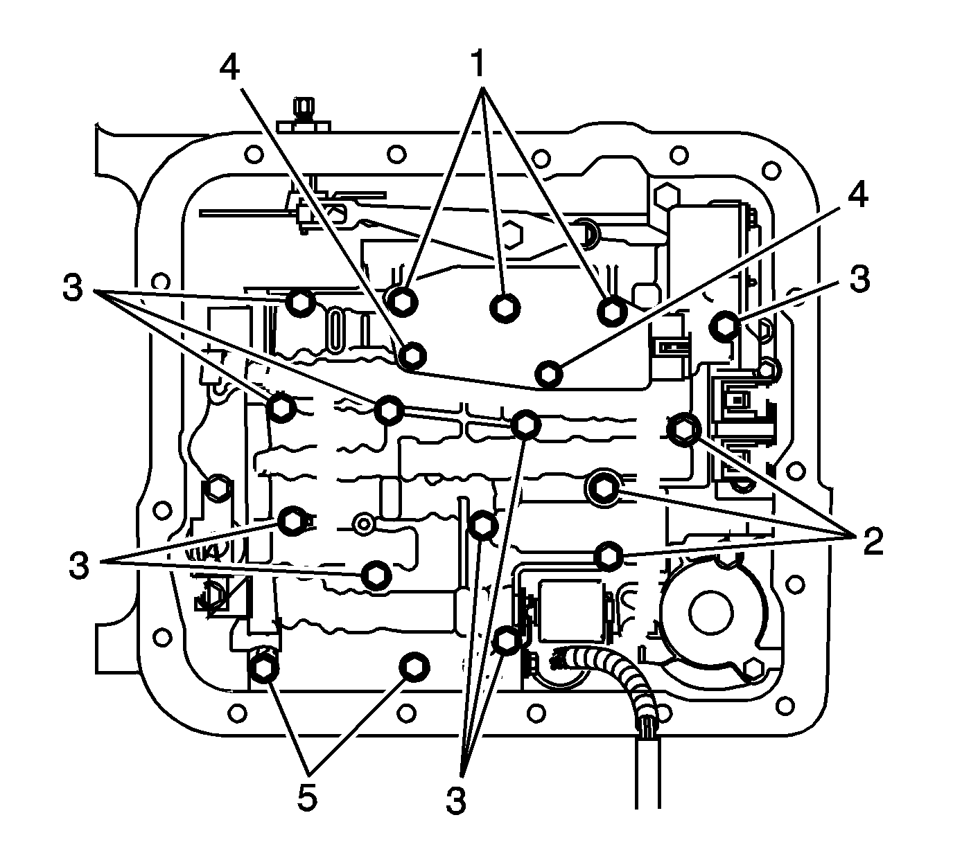
Notice: Do not over-tighten the bolts. Over-tightening the bolts will distort
the valve bores. Begin tightening from the center of the valve body tighten
the bolts in a outward direction.
- Check that all the valve body bolts are in the correct location.
Each bolt number refers to a specific bolt size, as indicated by the following list:
- Tighten the bolts from the center of the valve body working your way out in a spiral pattern to the outside edge.
Tighten
Tighten the bolts to 8-14N·m (6-10 lb ft).
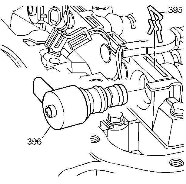
- Install the TCC PWM solenoid valve (396) and the solenoid retainer (395).
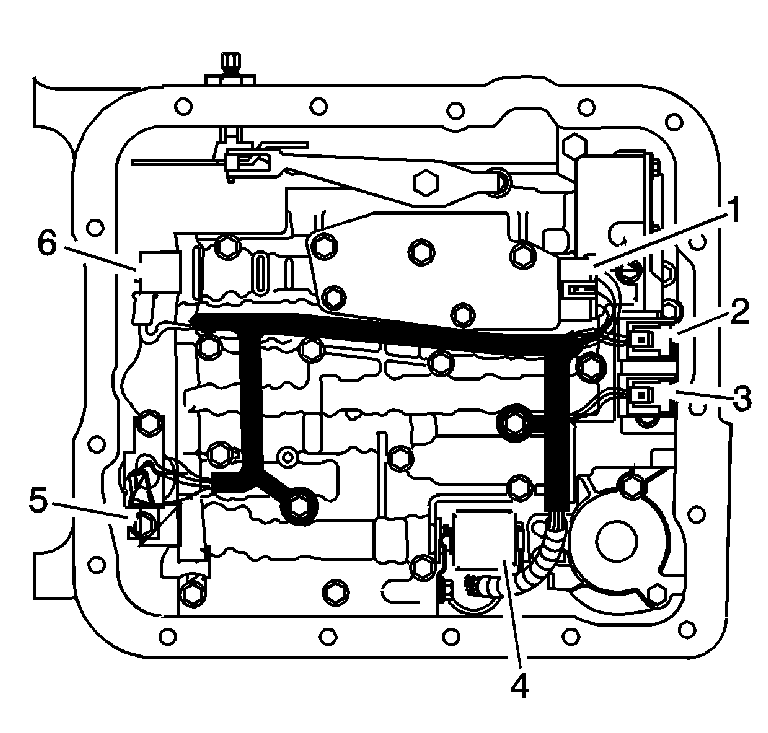
- Snap the wiring harness in place on the valve body bolts. Ensure the harness loom tab is located under the TFP
switch.
- Install the wiring connectors to the electrical components as indicated by the following list:
| • | 1 - Transmission Fluid Pressure (TFP) manual valve position switch |
| • | 4 - Pressure Control Solenoid (PCS) |
| • | 5 - Torque Converter Clutch Pulse Width Modulation (TCC PWM) Solenoid |


