For 1990-2009 cars
Tools Required
J 33163 Valve Tray Set
- Position the control valve body on the work table so that the main valve body is facing up.
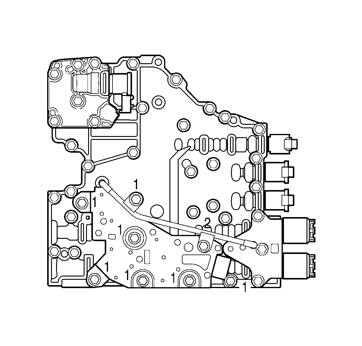
- Remove 6 bolts (1) and one bolt (2) retaining the reverse signal pipe and transmission fluid pressure (TFP) switch to the main valve body.
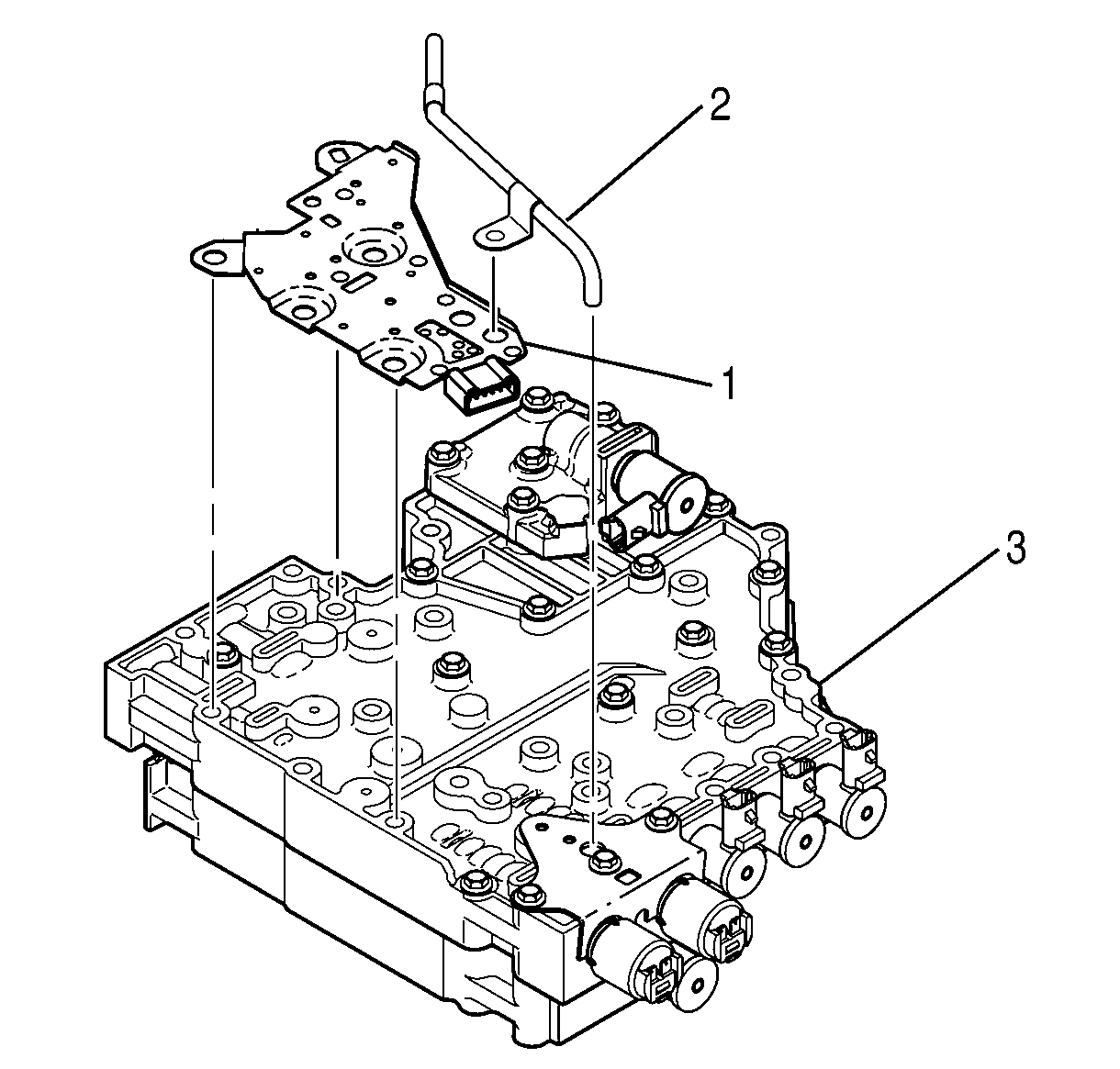
- Remove the reverse signal pipe (2) from the main valve body (3).
- Remove the TFP switch (1) from the main valve body (3).
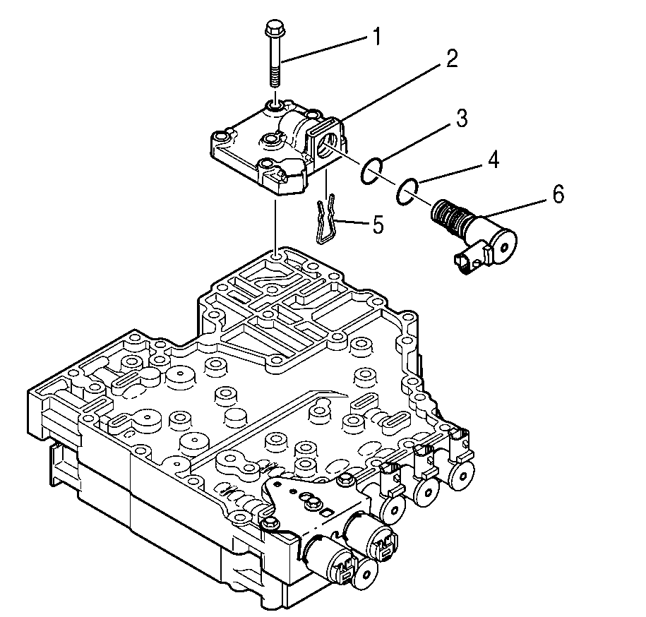
- Remove 2 bolts (1) retaining the modulated main pressure solenoid G valve body.
- Remove the modulated main pressure solenoid G body assembly (2).
- Remove the modulated main pressure solenoid G retainer (5) from the bottom of the valve body.
- Remove the modulated main pressure solenoid G (3).
- Remove 2 O-rings (4) from the modulated main pressure solenoid G (3).
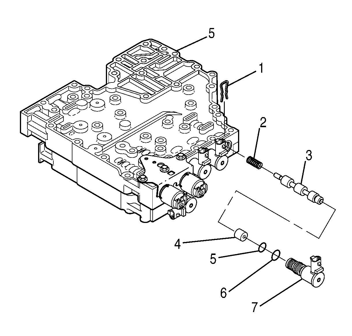
- Remove the torque converter clutch pulse width modulated (TCC PWM) solenoid retainer (1).
- Remove the TCC PWM solenoid (7), sleeve (4), valve (3), and spring (2).
- Remove the O-rings (5, 6) from the TCC PWM solenoid (7).
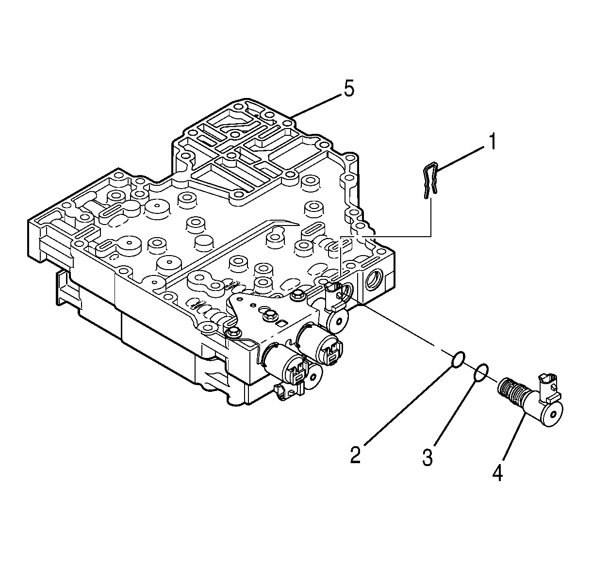
- Remove the shift solenoid D retainer (1).
- Remove the shift solenoid D (4).
- Remove the O-rings (2, 3) from the shift solenoid D (4).
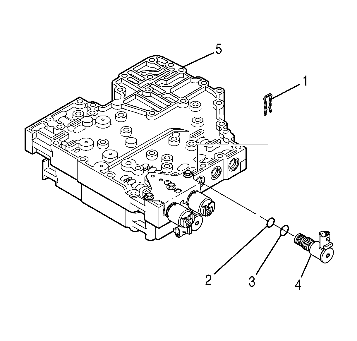
- Remove the shift solenoid E retainer (1).
- Remove the shift solenoid E (4).
- Remove the O-rings (2, 3) from the shift solenoid E (4).
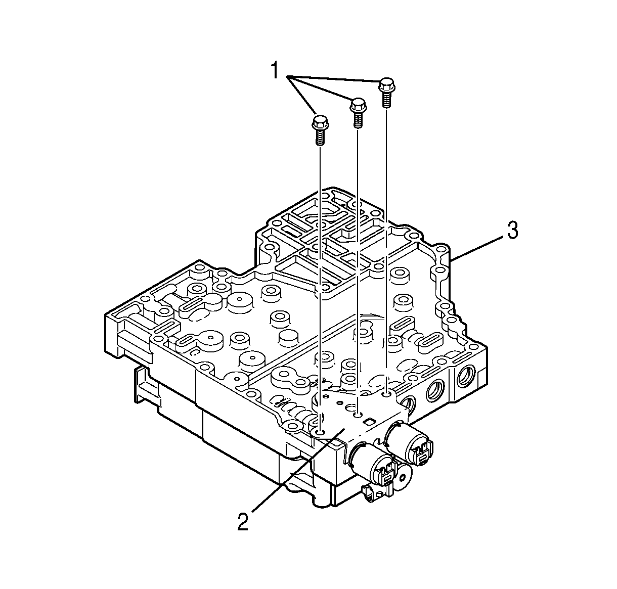
- Remove 3 bolts (1) that retain the pressure control valve retaining bracket (2) to the main valve body (3).
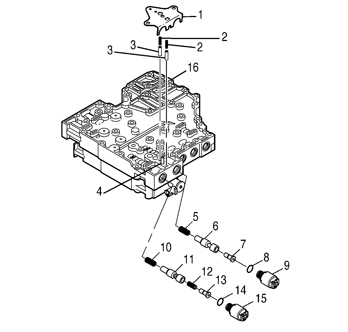
- Remove the pressure control valve retaining bracket (1), 2 accumulator springs (2), and 2 accumulator plugs (3).
- Remove the pressure control solenoid A (15), valve (13), spring (12), if present, valve (11), and spring (10).
- Remove the pressure control solenoid B (9), valve (7), valve (6), and spring (5).
- Remove the O-ring (14) from the pressure control solenoid A (15).
- Remove the O-ring (8) from the pressure control solenoid B (9).
- Position the control valve body on the work table so that the shift valve body (1) is facing up.
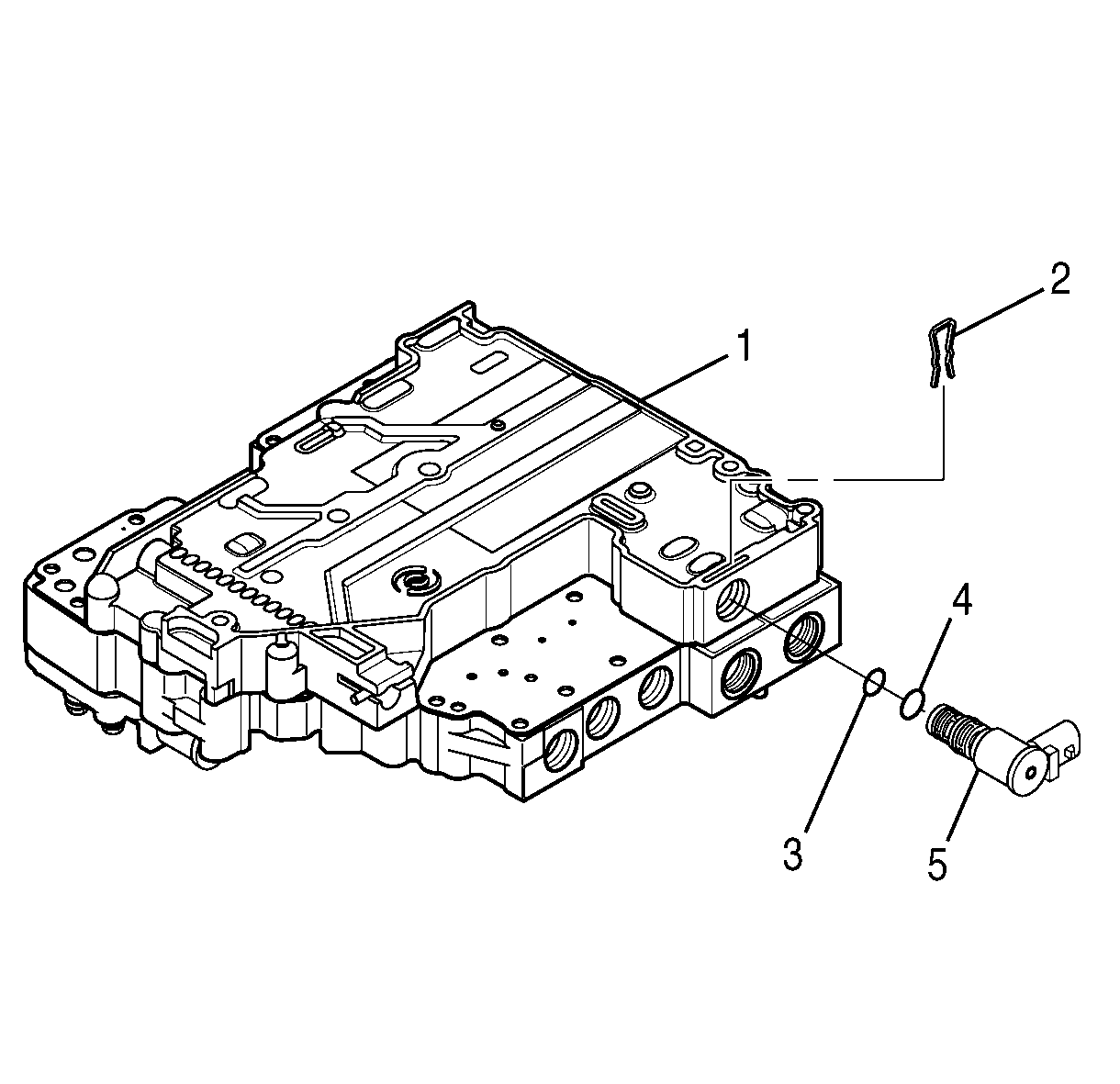
- Remove the shift solenoid C retainer (2).
- Remove the shift solenoid C (5).
- Remove the O-rings (3, 4) from the shift solenoid C (5).
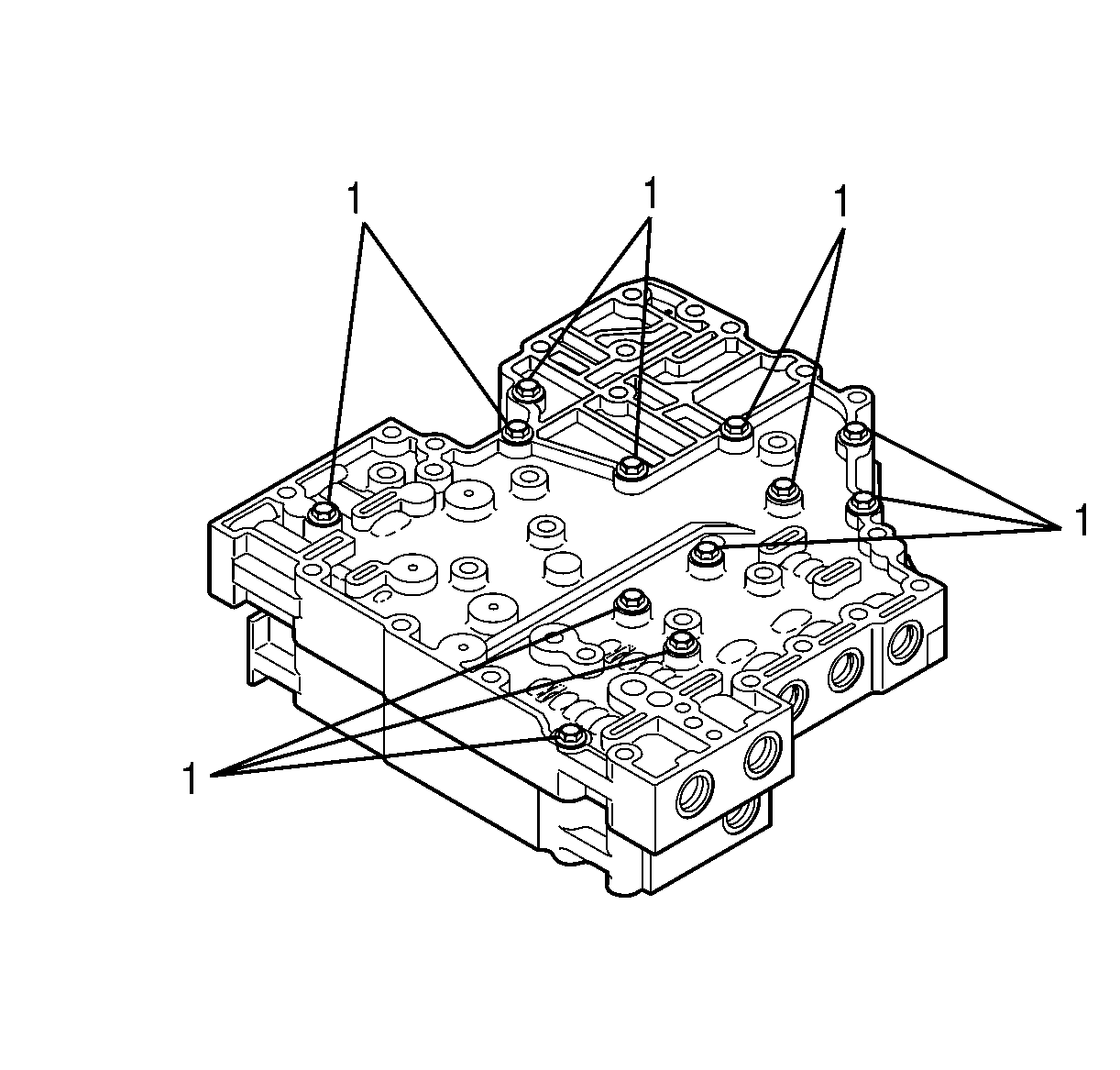
- Remove 11 bolts (1) retaining the shift valve body and the main valve body together.
- Position the control valve body on the work table so that the main valve body is facing up.
- Reinstall 4 bolts (1) so that the bolts are partially threaded into the shift valve body and protrude from the main valve body.
- Position the control valve body on edge so that the top and bottom are vertical.
- Gently tap the bolts until the module separates.
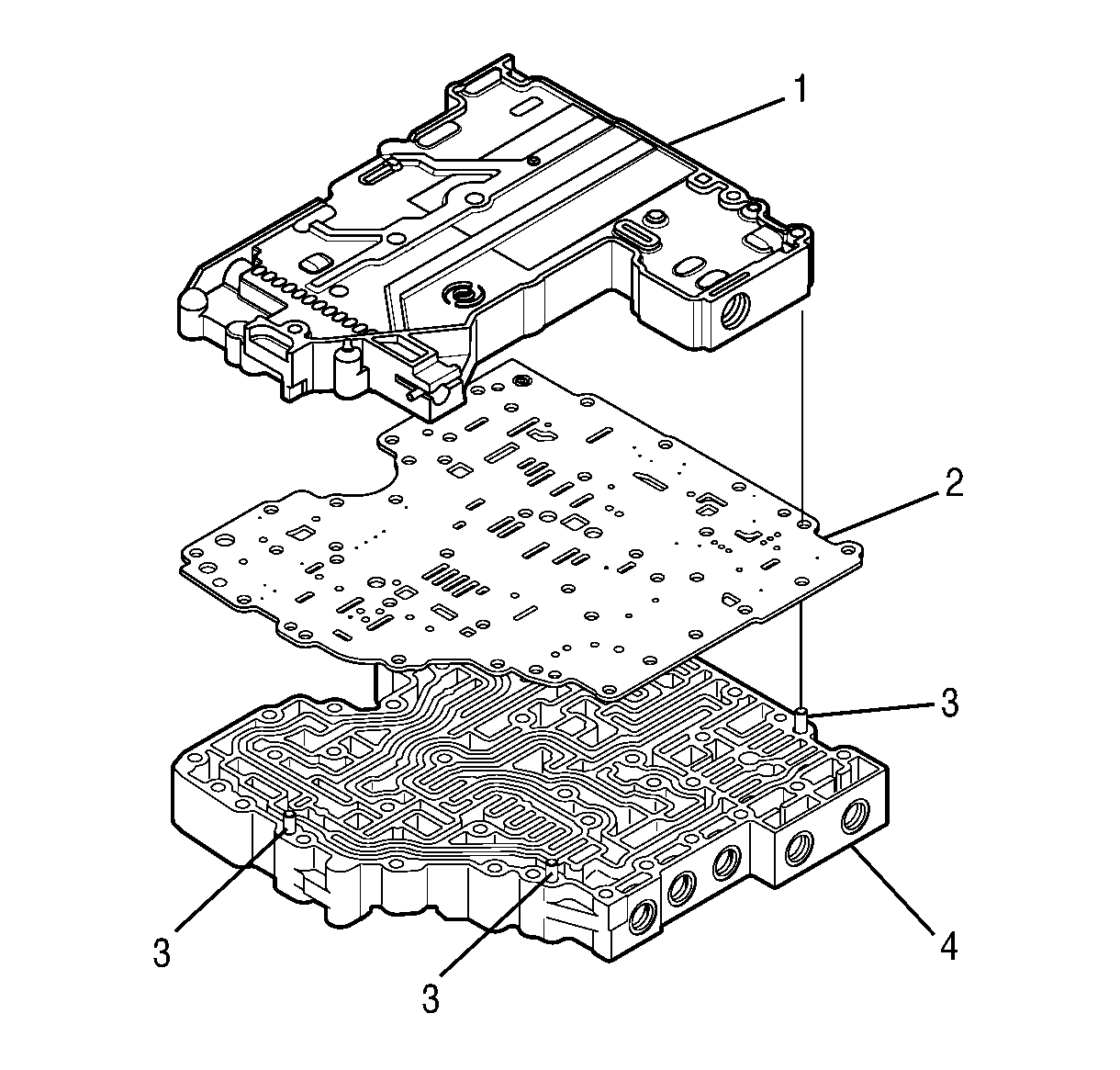
- Position the control valve assembly on the work table so that the shift valve body (1) is facing up.
- Separate the shift valve body assembly (1), the separator plate (2), and the main valve body assembly (4).
Important: To help prevent confusing parts on reassembly, use J 33163 to store the removed control valve assembly valves, springs, and stops.
