For 1990-2009 cars
Tools Required
J 26900-5 Vernier Caliper
- Remove the following components from the valve body:
- Remove the following lower valve body plate components from the valve body:
- Remove the following TCC lock-up control valve plate components from the valve body:
- Remove the following pressure relief valve components while depressing the retainer:
- Remove the following TCC solenoid components:
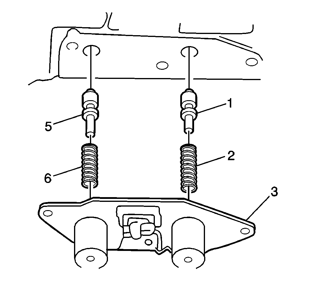
- Remove the following shift solenoid components:
- Remove the following TCC lock-up control sleeve components while depressing the sleeve:
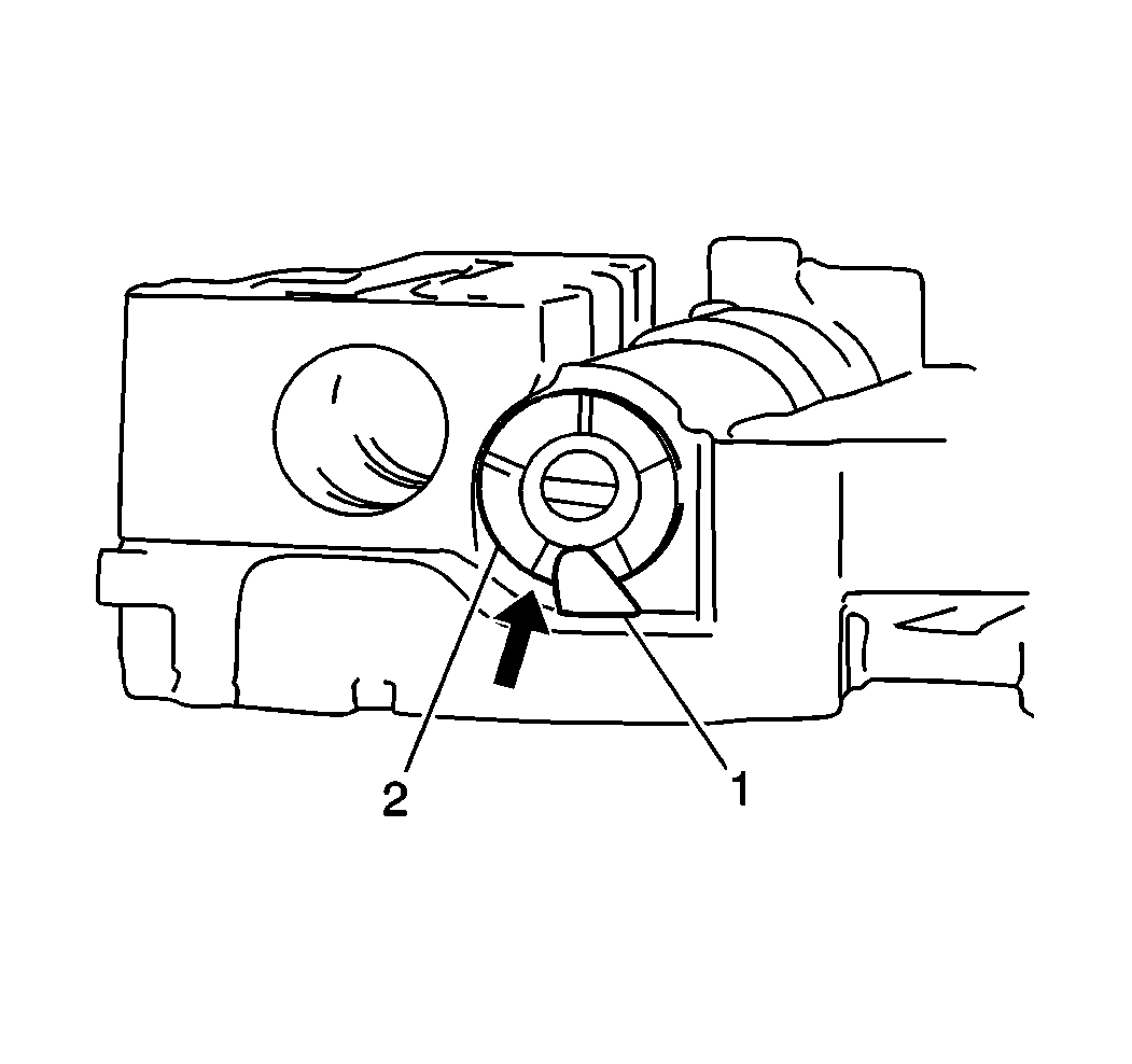
- Remove the primary regulator valve retainer (1) using a magnet.
- Using a magnet, remove the following primary regulator valve components while depressing the sleeve:
- Clean all upper valve body components.
- Allow the components to air dry.
- Inspect all valves for cracks, scoring, or other damage. Replace as necessary.
- Inspect all valve springs for distortion or damage. Replace as necessary.
- Inspect all valve bores for cracks or scoring. Replace as necessary.
- Measure the free length and the outer coil diameter of all lower valve body springs using the J 26900-5 .
- If any spring is not within the specifications as listed in the following table, replace as necessary. Refer to the Lower Valve Body Spring Specifications portion of Control Valve Lower Body Spring Specifications .
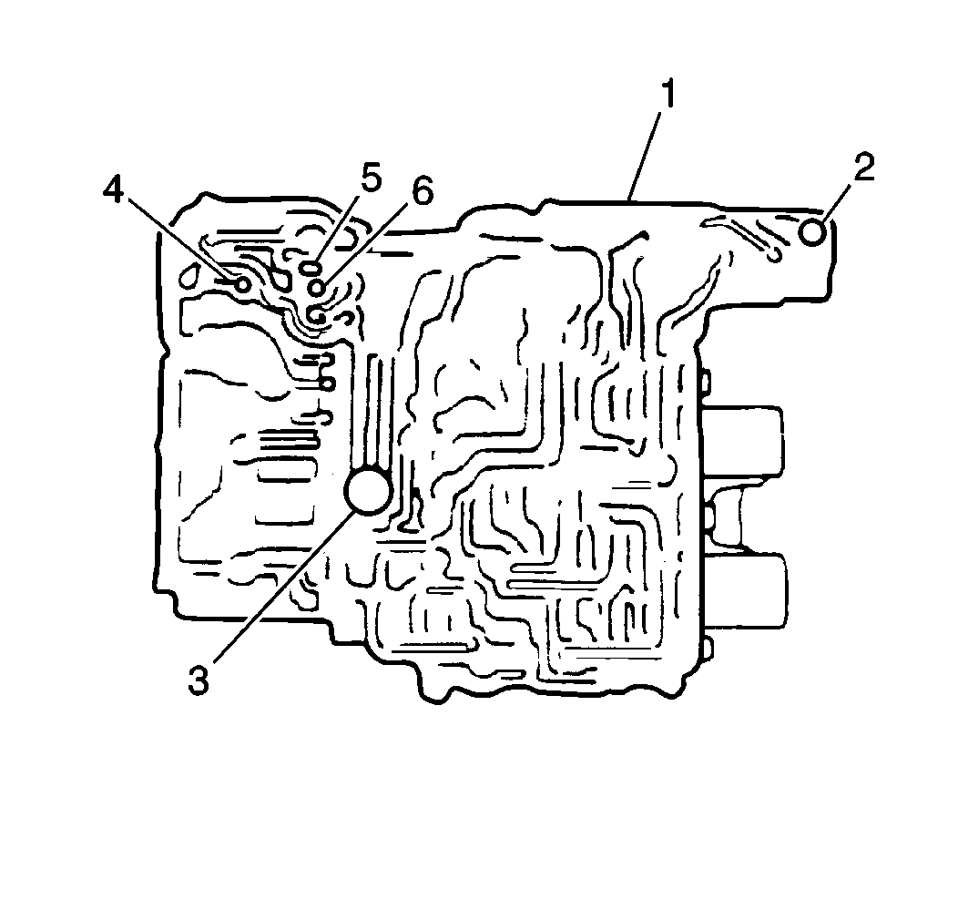
Important: When disassembling the valve body halves, keep all valve springs, spring seats and plugs within their respective valves. Most valve springs are of different sizes and CANNOT be interchanged. Verify that all parts are clean and dry before assembly.
| • | The bypass valve (3) |
| • | The bypass valve spring |
| • | The check ball (6) |
| • | The valve dampening spring |
| • | The valve body ball (2) |
| • | The ball valve spring |
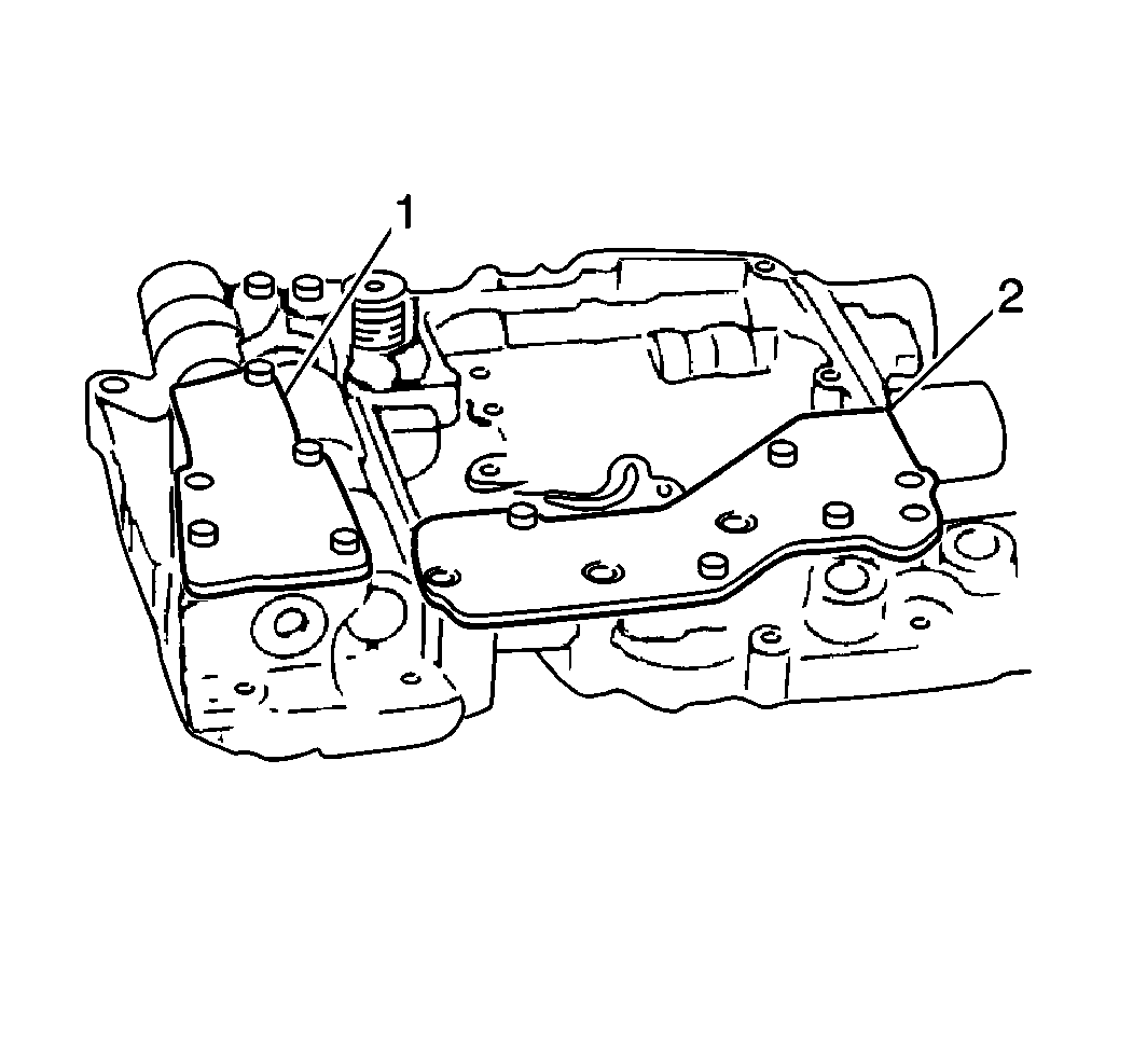
| • | The bolts |
| • | The gasket |
| • | The plate (1) |
| • | The bolts |
| • | The gasket |
| • | The plate (2) |
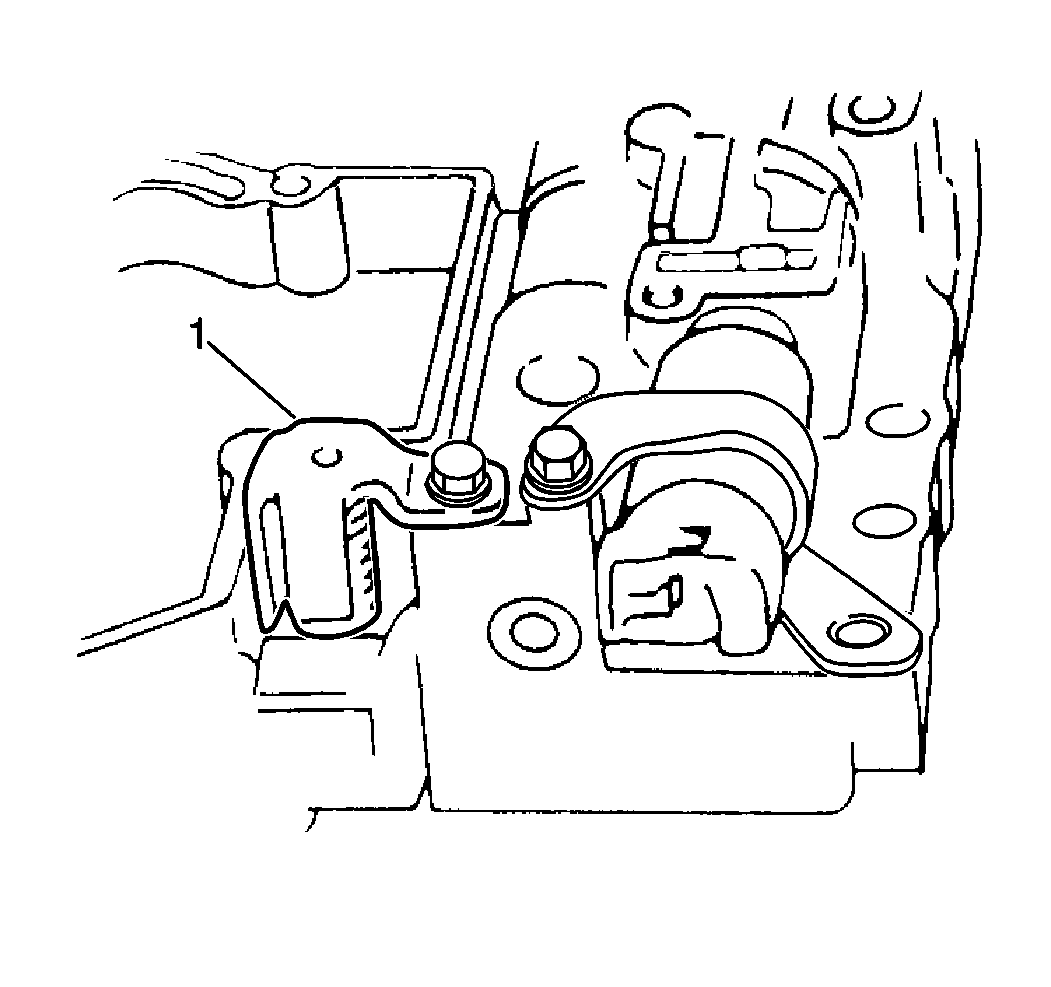
| • | The bolt |
| • | The retainer (1) |
| • | The spring |
| • | The ball |
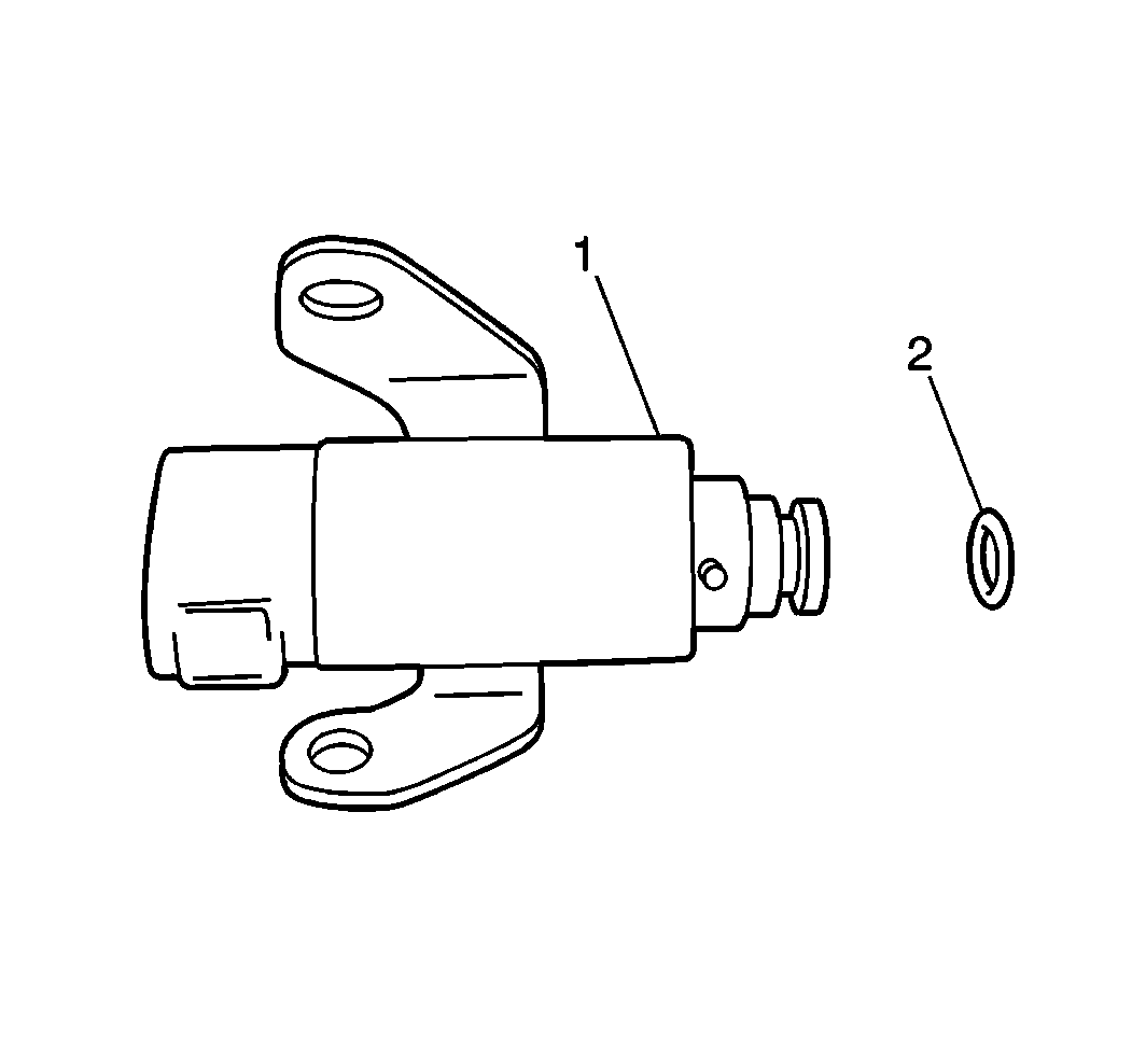
| • | The bolt |
| • | The solenoid (1) |
| • | The O-ring (2) |
| • | The bolts |
| • | The solenoid (3) |
| • | The gasket |
| • | The low coast modulator valve spring (6) |
| • | The intercoast modulator valve spring (2) |
| • | The intermediate coast modulator valves (5) |
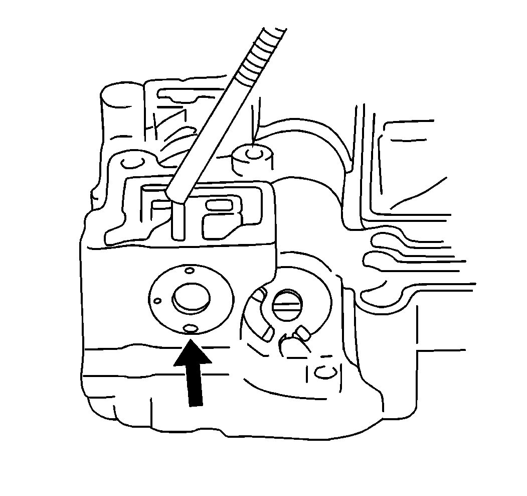
| • | The locating pin (using a magnet) |
| • | The sleeve |
| • | The spring |
Important: There are four step positions on the primary regulator valve sleeve (2). Note the position of the sleeve for assembly.
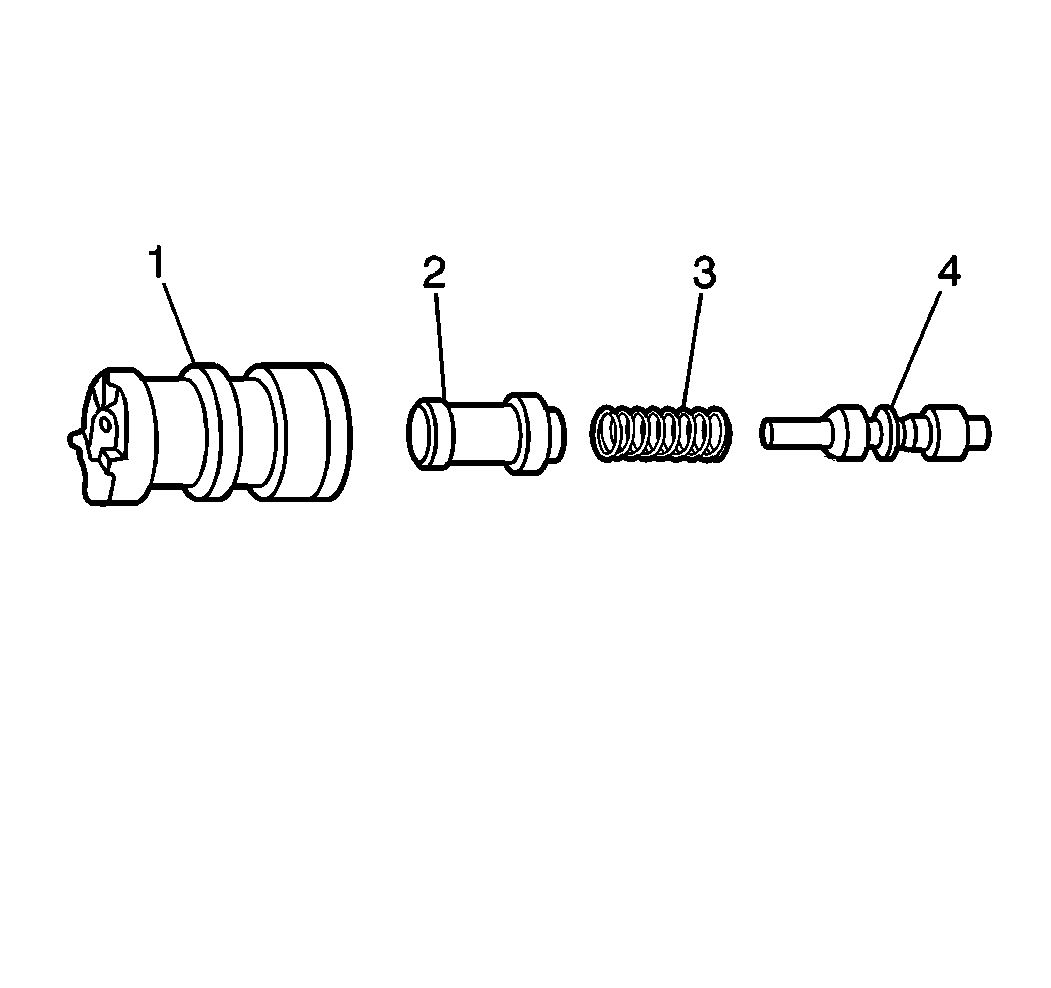
| • | The retainer |
| • | The sleeve (1) |
| • | The plunger (2) |
| • | The spring (3) |
| • | The valve (4) |