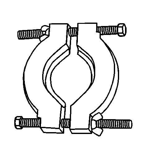
Tools Required
| • | J 36513 Gear
and Bearing Separator Plate |
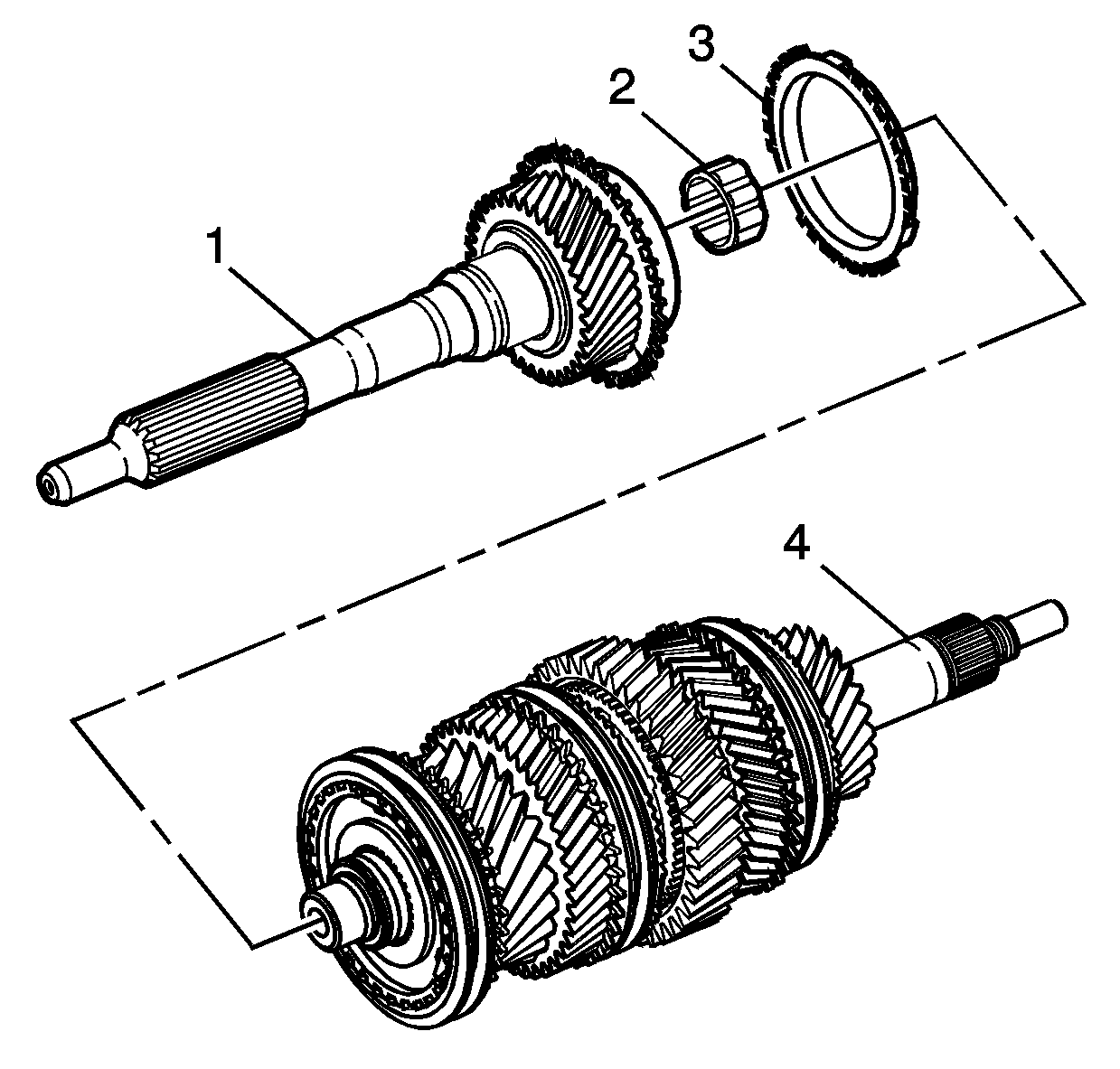
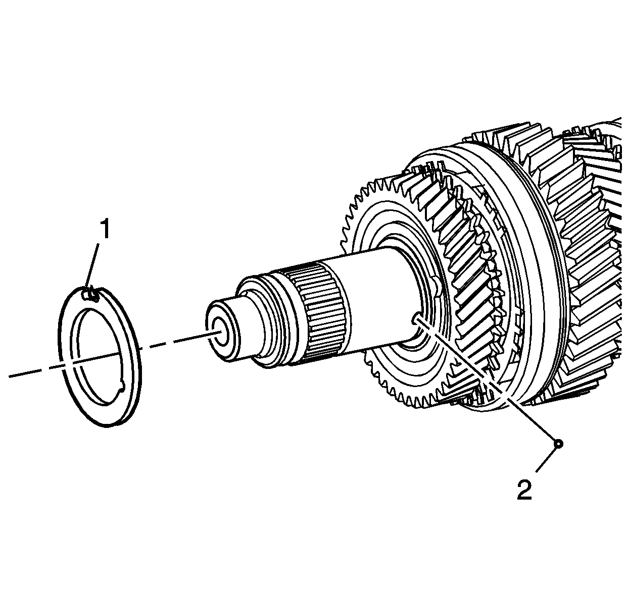
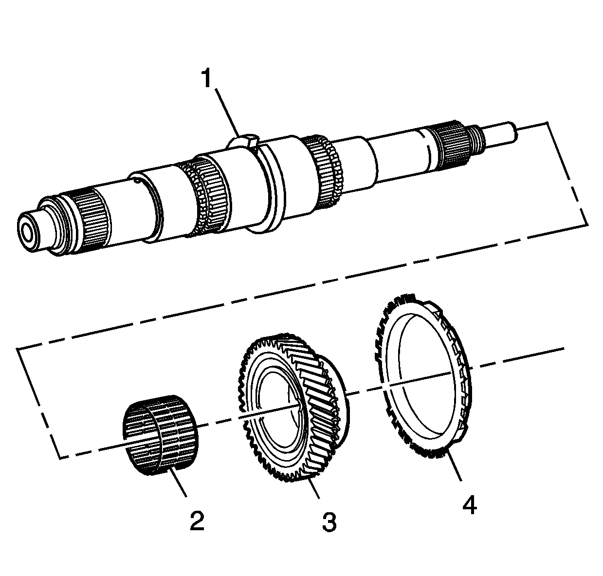
- Remove
the mainshaft input gear (1), bearing (2) and synchromesh
ring (3) from the mainshaft (4).
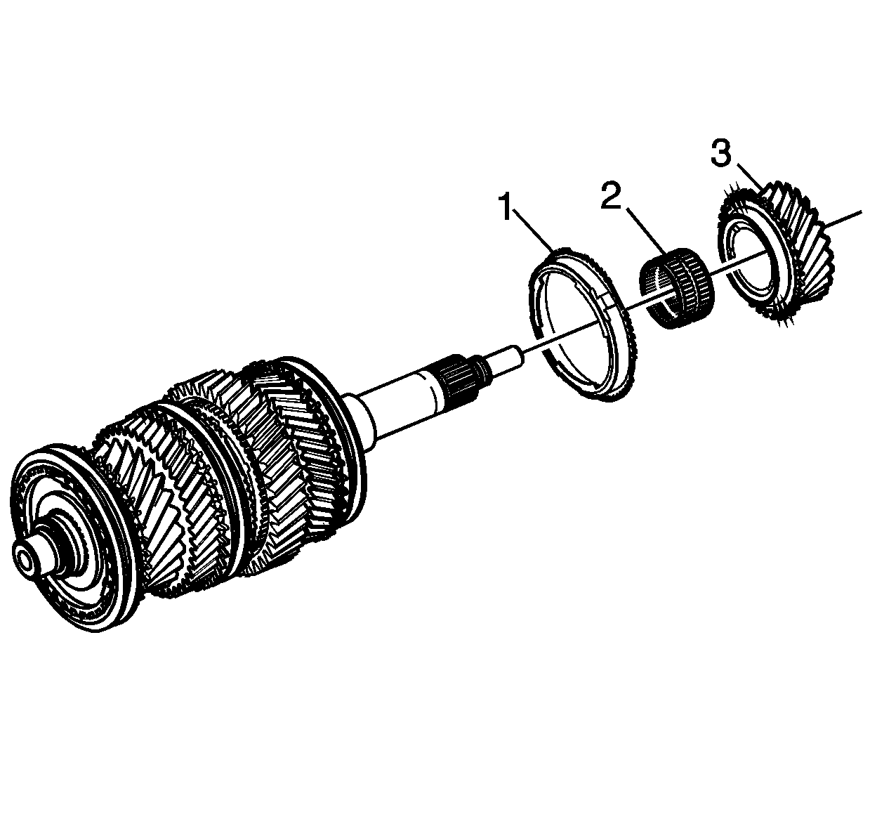
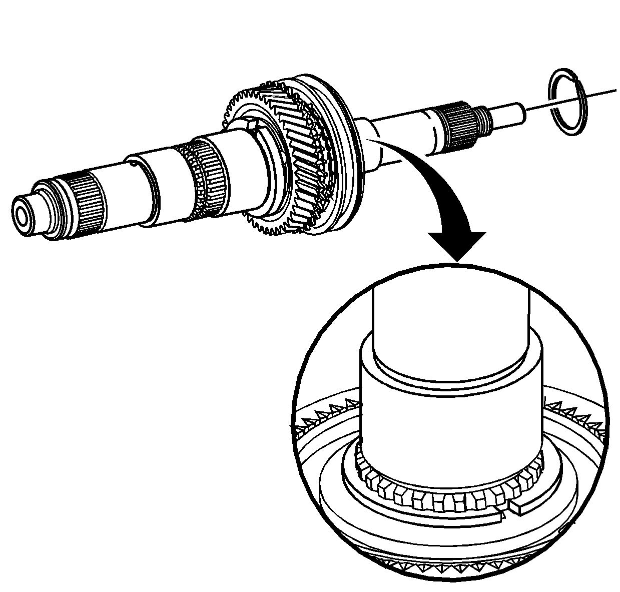
- Remove the 5th speed constant mesh gear (3),
synchromesh ring (1) and caged needle bearing (2) from the
rear of the mainshaft.
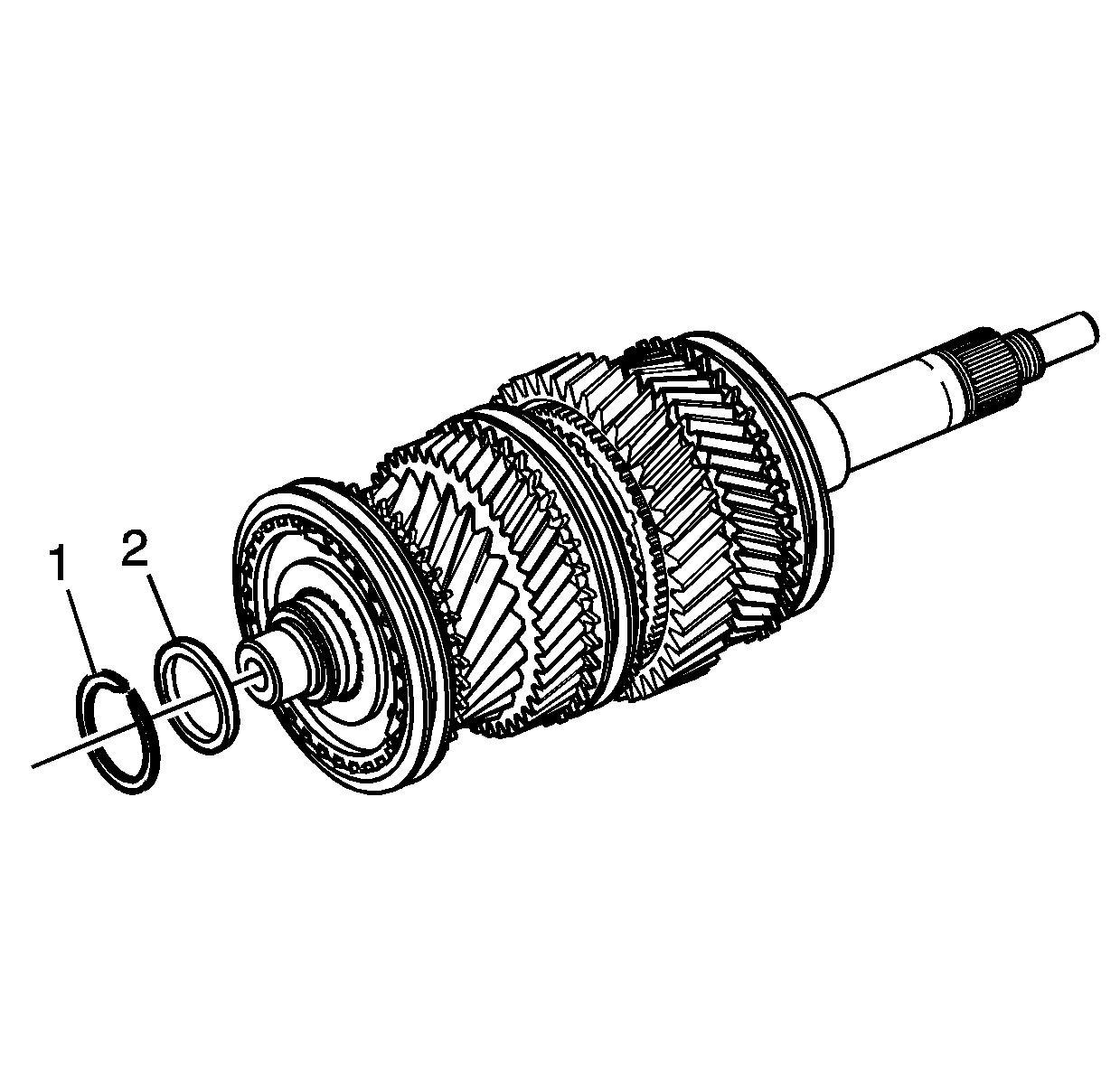
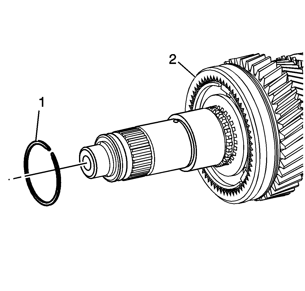
- Remove the snap ring (1) from the input
gear end of the mainshaft.
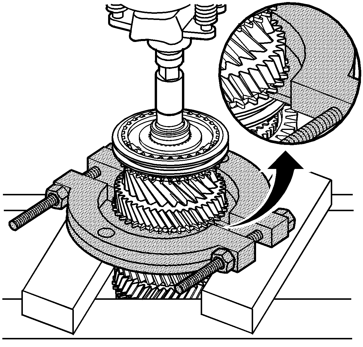
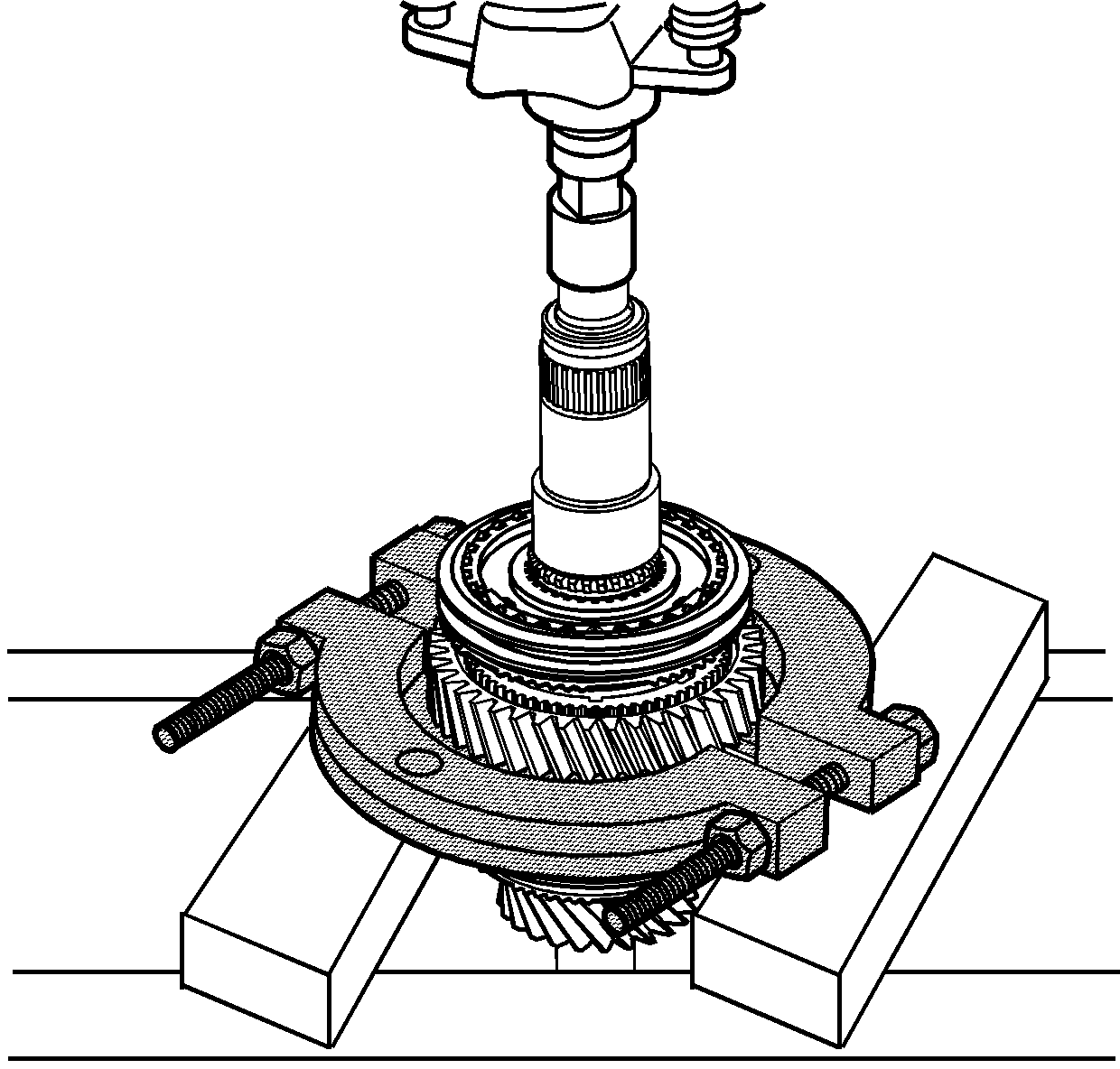
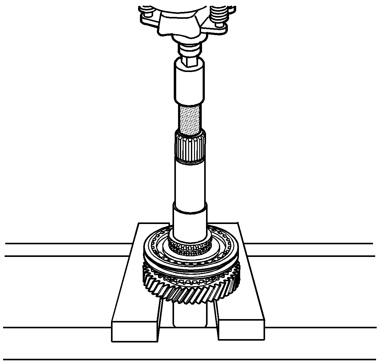
- Insert
the J 36513
under the
dog clutch teeth of the 2nd speed gear, ensuring that both halves are fully
installed.
- Support the J 36513
in a press and press the mainshaft from the following components:
| • | 3rd/4th gear synchromesh assembly |
| • | 3rd speed gear and synchromesh ring |
| • | 3rd speed gear, caged needle roller bearing |
| • | 3rd speed gear, roller bearing sleeve |
| • | 2nd speed gear, caged needle roller bearing |
Important: The thrust washer locating ball (2), may fall out during the
pressing operation.
- As the synchromesh hub and roller bearing sleeve are both interference
fits on the mainshaft, some force will be required to remove these components.
- Remove the thrust washer (1).
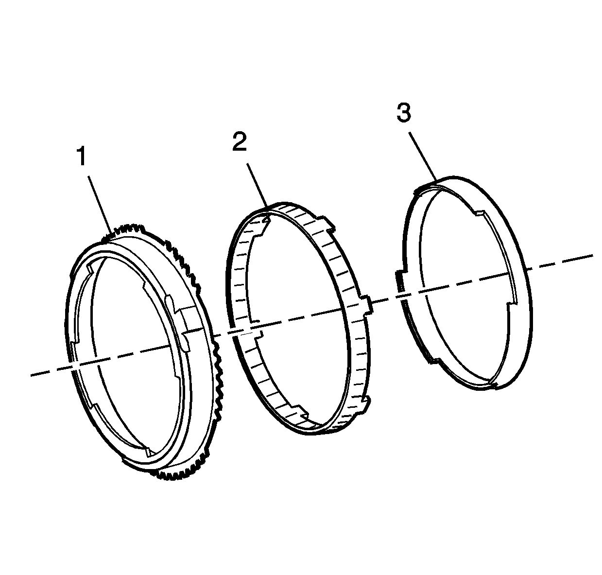
- Remove
the three part synchromesh rings (1, 2, 3) from the 1st/2nd synchromesh
assembly.
- Remove the snap ring (1) from the 1st/2nd
gear synchromesh hub (2).
- Place the J 36513
under the 1st speed gear, press the mainshaft from the 1st/2nd
speed synchromesh assembly, 1st speed synchromesh ring, cone ring, friction
ring, 1st speed gear and needle roller bearing.
- Remove the 5th/reverse speed synchromesh hub
snap ring from the mainshaft.
- Install the J 45006
over the output shaft to prevent shaft damage.
- Using a press, press the mainshaft from the 5th/reverse speed
synchromesh assembly, reverse synchromesh ring and reverse constant mesh
gear.
- Remove the 5th/reverse synchromesh hub and synchromesh
ring (4).
- Remove the reverse speed gear (3) and the selective caged
needle roller bearing (2) from the mainshaft (1).