Drive Pinion Flange/Yoke and/or Oil Seal Replacement All Except 9.75 Inch Axle
Tools Required
| • | J 8614-01 Flange/Pulley Holding Tool |
| • | J 22388 Pinion Oil Seal Installer - Rear (8.6 inch, 9.5 inch axle) |
| • | J 44414 Pinion Seal Installer (10.5 inch axle) |
Removal Procedure
- Raise the vehicle. Refer to Lifting and Jacking the Vehicle in General Information.
- Remove the tire and wheel assemblies (8.6 inch, 9.5 inch axles). Refer to Tire and Wheel Removal and Installation in Tires and Wheels.
- Remove the rear brake calipers (8.6 inch, 9.5 inch axles). Refer to Rear Brake Caliper Replacement in Disc Brakes.
- Remove the brake rotors (8.6 inch, 9.5 inch axles). Refer to Rear Brake Rotor Replacement in Disc Brakes.
- Remove the axle shafts (10.5 inch axle). Refer to Rear Axle Shaft and/or Gasket Replacement .
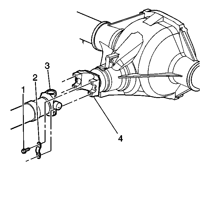
- Reference mark the rear propeller shaft (3) to the rear axle pinion yoke (4).
- Disconnect the propeller shaft from the axle.
- Measure the amount of torque required to rotate the pinion. Use an inch-pound torque wrench. Record this measurement for reassembly. This will give the combined preload for the following components:
- Draw 2 arrows pointing at each other, one on the pinion stem, the other on the pinion yoke.
- Record the number of exposed threads on the pinion stem for reference.
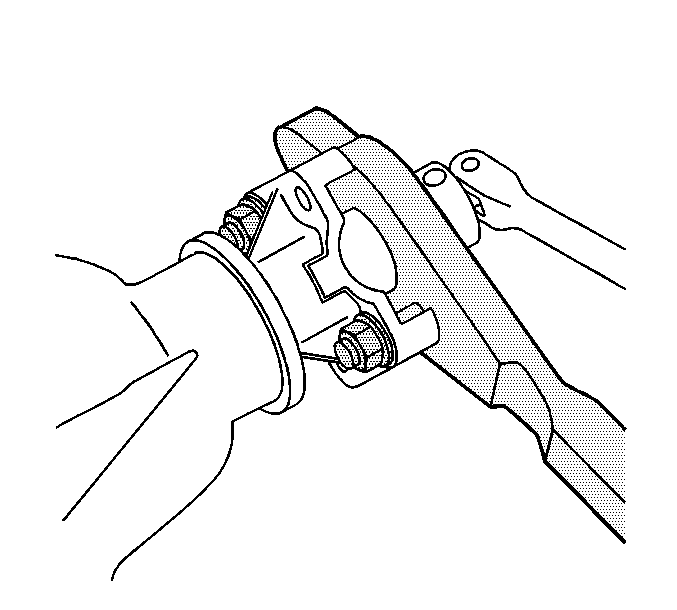
- Install the J 8614-01 as shown.
- Remove the pinion nut while holding the J 8614-01 .
- Remove the washer.
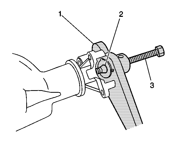
- Install the J 8614-2 (2) and the J 8614-3 (3) into the J 8614-01 (1) as shown.
- Remove the pinion yoke by turning the J 8614-3 (3) clockwise while holding the J 8614-01 (1).
- Remove the pinion oil seal. Use a suitable seal removal tool. Do not damage the housing.
Important: Observe and mark the positions of all the driveline components, relative to the propeller shaft and the axles, prior to disassembly. These components include the propeller shafts, drive axles, pinion flanges, output shafts, etc. Reassemble all the components in the exact places in which you removed the parts. Follow any specifications, torque values, and any measurements made prior to disassembly.
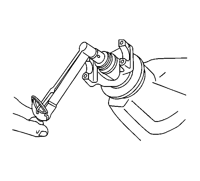
Wrap the bearing caps with tape in order to prevent the loss of bearing rollers.
Support the propeller shaft as necessary.
| • | The pinion bearings |
| • | The pinion pilot bearing (10.5 inch axle) |
| • | The pinion oil seal |
| • | The differential case bearings |
| • | The axle bearings (8.6 inch, 9.5 inch axles) |
| • | The axle seals (8.6 inch, 9.5 inch axles) |
Use a container in order to retrieve the lubricant.
Installation Procedure
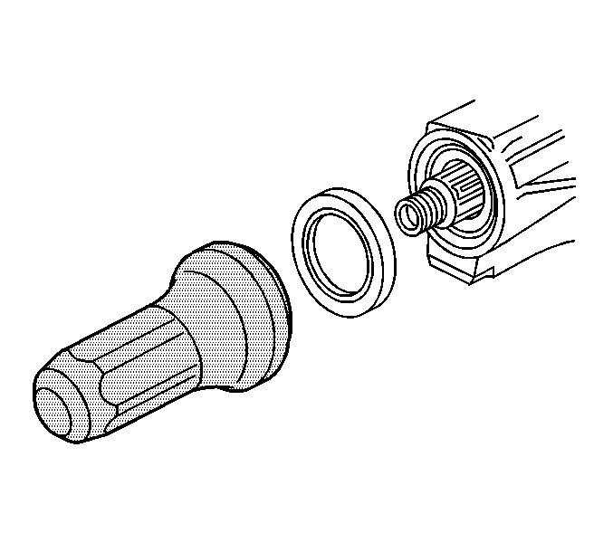
- Install a new pinion oil seal using theJ 22388 or the J 44414 .
- Apply sealant, GM P/N 12346004 (Canadian P/N 10953480) or equivalent, to the splines of the pinion yoke.
- Install the pinion yoke.
- Seat the pinion yoke onto the pinion shaft by tapping it with a soft-faced hammer until a few pinion shaft threads show through the yoke.
- Install the washer and a new pinion nut.
- Install the J 8614-01 onto the pinion yoke as shown.
- Tighten the pinion nut while holding the J 8614-01 .
- Measure the rotating torque of the pinion. Compare this measurement with the rotating torque recorded during removal.
- Once the specified torque is obtained, rotate the pinion several times to ensure the bearings have seated. Recheck the rotating torque and adjust if necessary.
- Install the propeller shaft (3) to the pinion yoke (4).
- Install the propeller shaft yoke retaining clamps and the bolts.
- Install the axle shafts (10.5 inch axle). Refer to Rear Axle Shaft and/or Gasket Replacement .
- Install the brake rotors (8.6 inch, 9.5 inch axles). Refer to Rear Brake Rotor Replacement in Disc Brakes.
- Install the brake calipers (8.6 inch, 9.5 inch axles). Refer to Rear Brake Caliper Replacement in Disc Brakes.
- Install the tire and the wheel. Refer to Tire and Wheel Removal and Installation in Tires and Wheels.
- Inspect and add axle lubricant to the axle housing, if necessary. Refer to Rear Axle Lubricant Level Inspection .
- Lower the vehicle.
Align the marks made during removal.
Notice: Refer to Pinion Flange/Yoke Installation Notice in the Preface section.

Notice: Use the correct fastener in the correct location. Replacement fasteners must be the correct part number for that application. Fasteners requiring replacement or fasteners requiring the use of thread locking compound or sealant are identified in the service procedure. Do not use paints, lubricants, or corrosion inhibitors on fasteners or fastener joint surfaces unless specified. These coatings affect fastener torque and joint clamping force and may damage the fastener. Use the correct tightening sequence and specifications when installing fasteners in order to avoid damage to parts and systems.
Important: If the rotating torque is exceeded, the pinion will have to be removed and a new collapsible spacer installed.
Tighten
Tighten the nut until the pinion end play is just
taken up. Rotate the pinion while tightening the nut to seat the bearings.

Tighten
Tighten the nut in small increments, as needed,
until the rotating torque is 0.40-0.57 N·m (3- 5 lb in)
greater than the rotating torque recorded during removal.

Align the reference marks made during removal.
Tighten
Tighten the propeller shaft yoke retaining clamp
bolts to 25 N·m (18 lb ft).
Drive Pinion Flange/Yoke and/or Oil Seal Replacement 9.75 Inch Axle
Tools Required
| • | J 8614-01 Flange and Pulley Holding Tool |
| • | J 45710 Pinion Bearing Oil Seal Installer |
Removal Procedure
- Raise the vehicle. Refer to Lifting and Jacking the Vehicle in General Information.
- Disconnect the propeller shaft from the rear axle pinion yoke. Refer to Rear Propeller Shaft Replacement in Propeller Shaft.
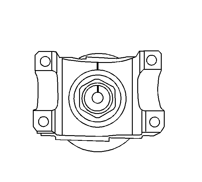
- Place an alignment mark between the pinion and the pinion yoke.
- Install the J 8614-01 as shown.
- Remove the pinion nut while holding the J 8614-01 .
- Remove the washer.
- Install the J 8614-2 (2) and the J 8614-3 (3) into the J 8614-01 (1) as shown.
- Remove the pinion yoke by turning the J 8614-3 (3) clockwise while holding the J 8614-01 (1).
- Remove the pinion oil seal. Use a suitable seal removal tool. Do not damage the axle housing.
Important: Observe and mark the positions of all the driveline components, relative to the propeller shaft and the axles, prior to disassembly. These components include the propeller shafts, drive axles, pinion flanges, output shafts, etc. Reassemble all the components in the exact places in which you removed the parts. Follow any specifications, torque values, and any measurements made prior to disassembly.

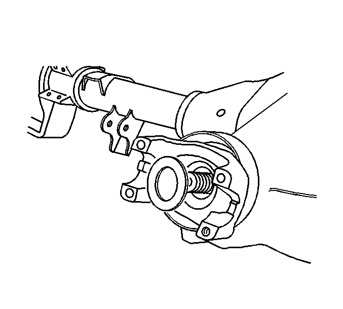

Use a container in order to retrieve the lubricant.
Installation Procedure
- Apply a light coat of axle lubricant, GM P/N 12378557 or equivalent meeting GM Specification 9986207, to the lip of the pinion seal.
- Install the new seal using the J 45710 .
- Install the pinion yoke.
- Seat the pinion yoke onto the pinion shaft by tapping it with a soft-faced hammer until a few pinion shaft threads show through the yoke.
- Install the washer.
- Install the new pinion nut
- Install the J 8614-01 onto the pinion yoke as shown.
- Tighten the pinion nut while holding the J 8614-01 .
- Install the propeller shaft to the rear axle pinion yoke. Refer to Rear Propeller Shaft Replacement in Propeller Shaft.
- Inspect and add axle lubricant to the axle housing, if necessary. Refer to Rear Axle Lubricant Level Inspection .
- Lower the vehicle.
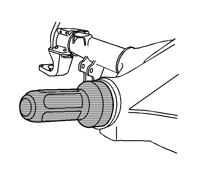
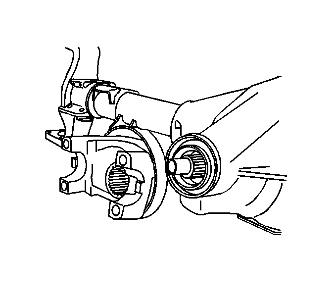
Notice: Refer to Pinion Flange/Yoke Installation Notice in the Preface section.

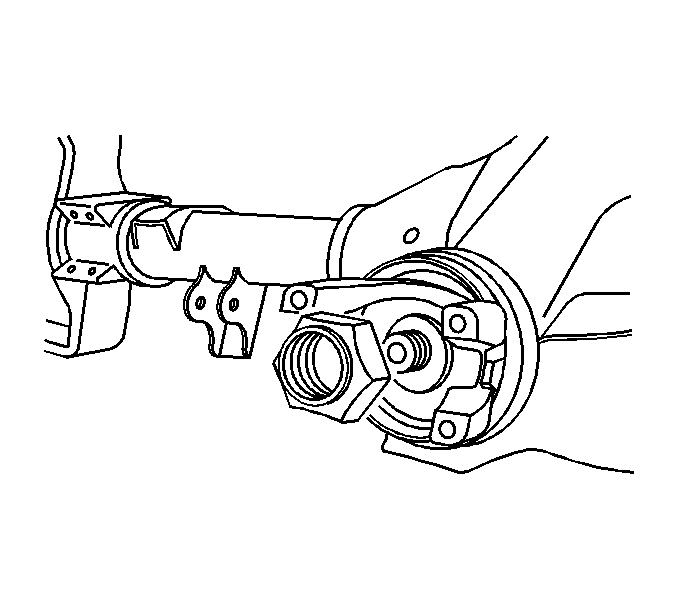

Notice: Refer to Fastener Notice in the Preface section.
Tighten
Tighten the pinion nut to 370 N·m (273 lb ft).