Removal Procedure
Caution: Refer to Brake Fluid Irritant Caution in the Preface section.
Notice: Refer to Brake Fluid Effects on Paint and Electrical Components Notice in the Preface section.
- Disconnect the negative battery cable. Refer to Battery Negative Cable Disconnection and Connection in Engine Electrical.
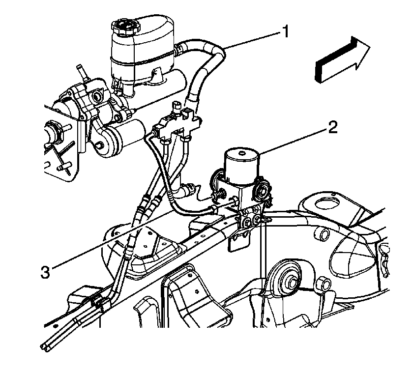
- Crimp the inlet hose (1) from the master cylinder to the Pre-Charge Pump (PCP) (2) to prevent fluid from leaking out and draining the master cylinder reservoir.
- Remove the inlet hose clamp from the PCP assembly inlet port.
- Remove the inlet hose (1) from the PCP assembly inlet port.
- Loosen and remove the brake fluid outlet pipe (3). Cap or plug the brake pipe to prevent contamination and brake fluid lose.
- Disconnect the PCP electrical connector from the vehicle connector harness.
- Remove the PCP electrical connector from the mounting bracket.
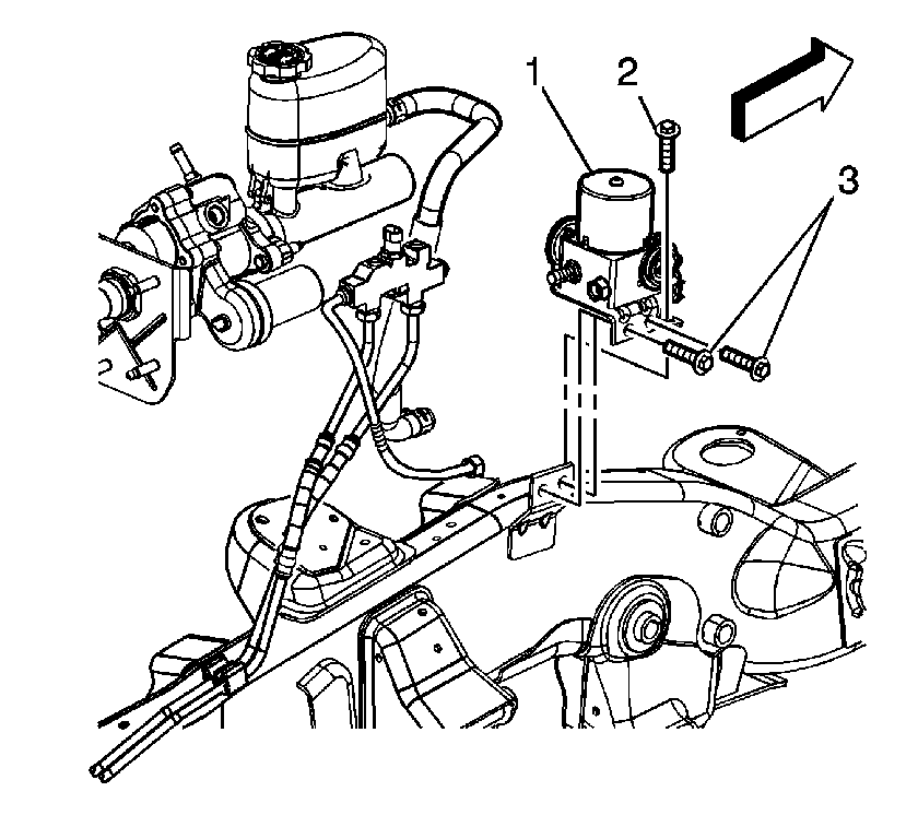
- Remove the PCP mounting bracket front bolt (2) and mounting bracket side bolts (3).
- Remove the PCP assembly (1) from the vehicle.

Notice: Avoid spilling brake fluid onto painted surfaces, electrical connections, wiring, or cables. Brake fluid will damage painted surfaces and cause corrosion to electrical components. If any brake fluid comes in contact with painted surfaces, immediately flush the area with water. If any brake fluid comes in contact with electrical connections, wiring, or cables, use a clean shop cloth to wipe away the fluid.
Important: The area around the pre-charge pump MUST be free from loose dirt to prevent contamination of disassembled ABS components.

Installation Procedure
- Install the PCP (1) into the vehicle. Ensure the bottom of the PCP motor is secured in the bottom mounting grommet on the PCP mounting bracket.
- Install the PCP front and side mounting bracket bolts (2,3).
- Install the PCP electrical connector to the mounting bracket. Check to insure the connector is locked into place.
- Connect the PCP electrical connector to the vehicle connector harness.
- Remove the cap or plug from the outlet pipe and install the outlet pipe (3) to the PCP (2).
- Install the inlet hose and clamp (1) to the PCP (2).
- Remove the crimping tool from the inlet hose.
- Connect the negative battery cable. Refer to Battery Negative Cable Disconnection and Connection in Engine Electrical.
- Fill the master cylinder reservoir. Refer to Master Cylinder Reservoir Filling in Hydraulic Brakes.
- Using a scan tool, perform a precharge pump bleed procedure. Refer to Antilock Brake System Automated Bleed Procedure .

Notice: Use the correct fastener in the correct location. Replacement fasteners must be the correct part number for that application. Fasteners requiring replacement or fasteners requiring the use of thread locking compound or sealant are identified in the service procedure. Do not use paints, lubricants, or corrosion inhibitors on fasteners or fastener joint surfaces unless specified. These coatings affect fastener torque and joint clamping force and may damage the fastener. Use the correct tightening sequence and specifications when installing fasteners in order to avoid damage to parts and systems.
Tighten
Tighten the bolts to 15 N·m (10 lb ft).

Tighten
Tighten the brake fluid outlet pipe nut to 25 N·m (18 lb ft).