For 1990-2009 cars
Tools Required
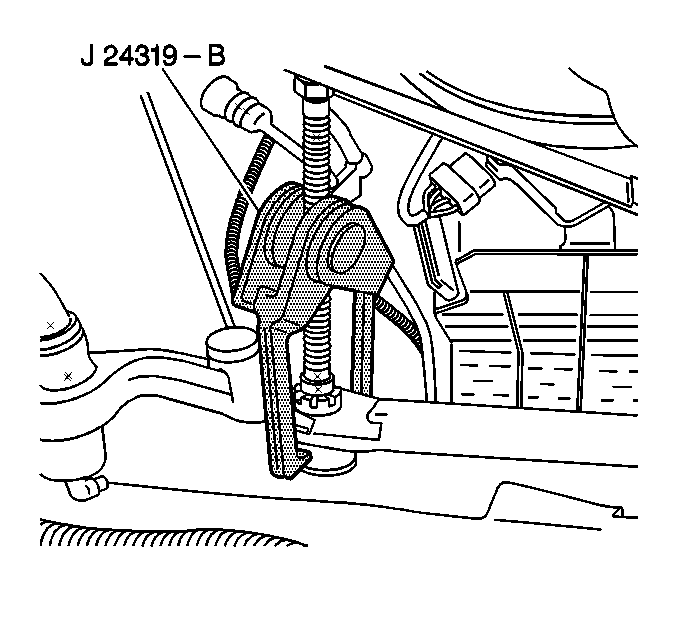
| • | J 24319-B Universal Steering Linkage Puller |
| • | J 29193 Steering Linkage Installer (12 mm) |
Removal Procedure
- Raise the vehicle. Support the vehicle with safety stands. Refer to Lifting and Jacking the Vehicle .
- Remove the engine protection shield, if equipped. Refer to Engine Protection Shield Replacement .
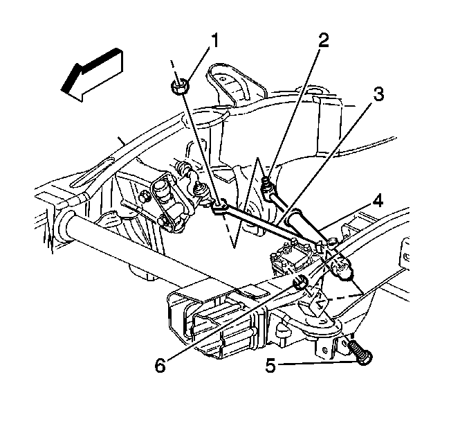
- Remove the steering linkage shock absorber (2) ball stud nut (1).
- Remove the shock absorber ball stud from the relay rod using the J 24319-B .
- Remove the shock absorber mounting bolt (5) and the nut (6).
- Remove the shock absorber (4) from the vehicle.
- Inspect the following parts:

Important: Do not reuse the nut.


Important: Do not reuse the nut.
| • | The shock absorber for leaks and damage |
| • | The mounting bolts and the nuts for damage or corrosion |
Installation Procedure
- Install the shock absorber (4).
- Install the mounting bolt (5) and a new prevailing torque nut (6).
- Install the shock absorber ball stud (2) to the relay rod (3).
- Install the J 29193 .
- Tighten the steering linkage installer in order to seat the ball stud in the relay rod.
- Remove the J 29193 .
- Install the prevailing torque nuts.
- Install the engine protection shield, if equipped. Refer to Engine Protection Shield Replacement .
- Lower the vehicle.

Notice: Refer to Fastener Notice in the Preface section.

Tighten
Tighten the installer to 54 N·m (40 lb ft).
Tighten
| • | Tighten the shock absorber mounting nut to 40 N·m (30 lb ft). |
| • | Tighten the ball stud nut to 40 N·m (30 lb ft). |