For 1990-2009 cars
Tools Required
| • | J 8433 Two Jaw Puller |
| • | J 21427-A Speedometer Gear Puller Adapter |
| • | J 36352 Speed Sensor Rotor Installer Kit |
Removal Procedure
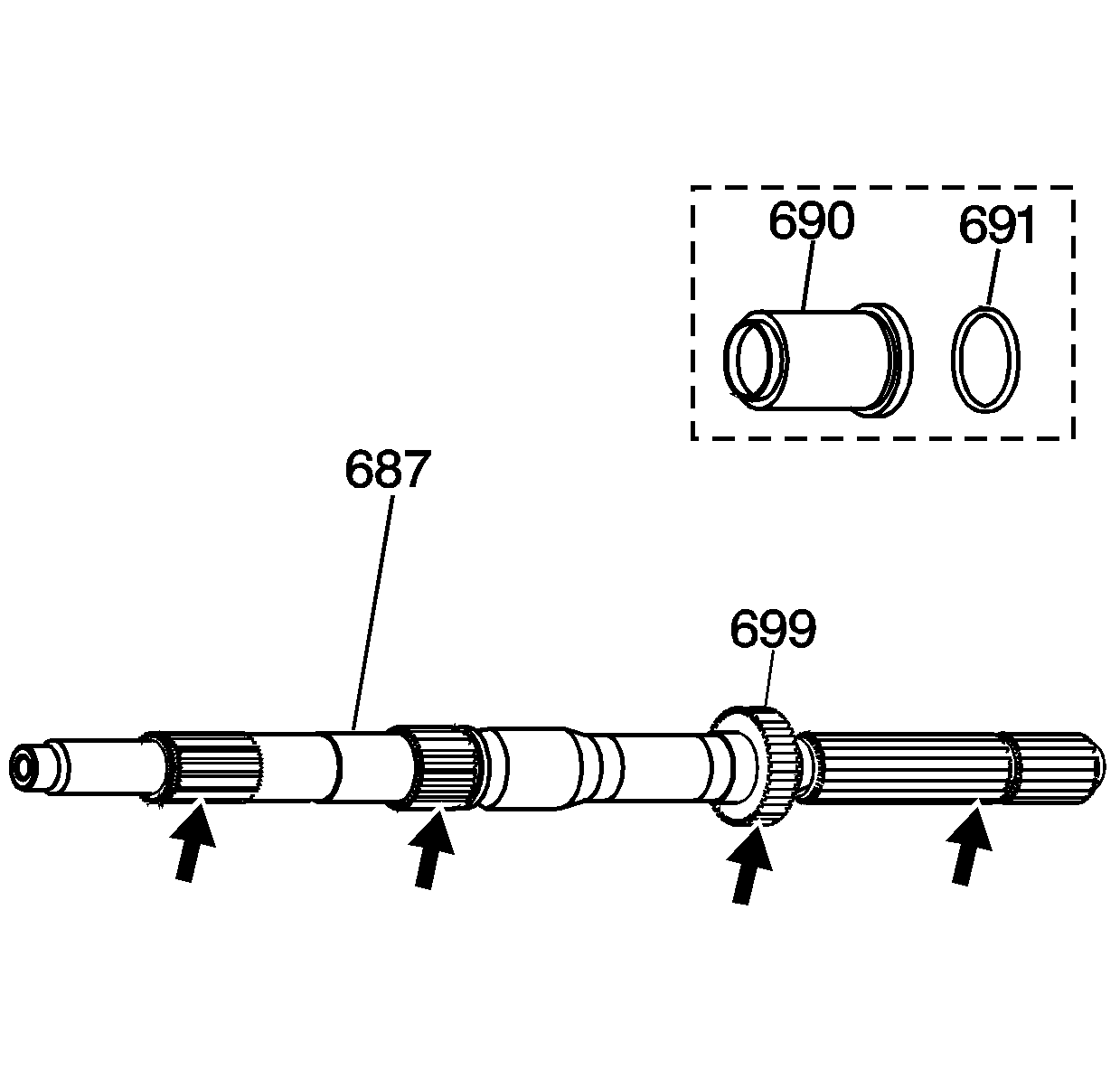
- Inspect the internal transmission speed sensor rotor (699) for cracks or damaged teeth.
- Inspect all splines on the output shaft (687) for cracks or damaged splines.
- Remove the output shaft seal (691) and the output shaft sleeve (690) (model dependent) 2WD units only.
- If the internal speed sensor rotor (699) is damaged, replace it.
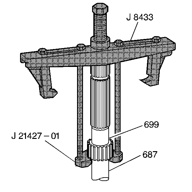
- Using J 8433 with J 21427-01 , remove the internal speed sensor rotor (699) from the output shaft (687).


Installation Procedure
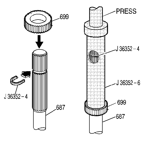
- Slip a new internal speed sensor rotor (699) over the output shaft splines.
- Install the J 36352-4 in the groove on the output shaft (687).
- Place the J 36352-6 on the output shaft (687). Press on the J 36352-6 until it contacts the J 36352-4 in the window (the J 36352-4 will be a positive stop for the J 36352-6 ).

Important: Do not re-use an internal speed sensor rotor that has been removed.