Powertrain
The powertrain has electronic controls to reduce exhaust emissions while maintaining excellent driveability and fuel economy. The powertrain control module (PCM) is the control center of this system. The PCM monitors numerous engine and vehicle functions. The PCM constantly looks at the information from various sensors and other inputs, and controls the systems that affect vehicle performance and emissions. The PCM also performs the diagnostic tests on various parts of the system. The PCM can recognize operational problems and alert the driver via the malfunction indicator lamp (MIL). When the PCM detects a malfunction, the PCM stores a diagnostic trouble code (DTC). The problem area is identified by the particular DTC that is set. The control module supplies a buffered voltage to various sensors and switches. Review the components and wiring diagrams in order to determine which systems are controlled by the PCM.
The following are some of the functions that the PCM controls:
| • | The engine fueling |
| • | The ignition control (IC) |
| • | The knock sensor (KS) system |
| • | The evaporative emissions (EVAP) system |
| • | The secondary air injection (AIR) system (if equipped) |
| • | The exhaust gas recirculation (EGR) system |
| • | The automatic transmission functions |
| • | The generator |
| • | The A/C clutch control |
| • | The cooling fan control |
Powertrain Control Module Function
The powertrain control module (PCM) constantly looks at the information from various sensors and other inputs and controls systems that affect vehicle performance and emissions. The PCM also performs diagnostic tests on various parts of the system. The PCM can recognize operational problems and alert the driver via the malfunction indicator lamp (MIL). When the PCM detects a malfunction, the PCM stores a diagnostic trouble code (DTC). The problem area is identified by the particular DTC that is set. The control module supplies a buffered voltage to various sensors and switches. The input and output devices in the PCM include analog-to-digital converters, signal buffers, counters, and output drivers. The output drivers are electronic switches that complete a ground or voltage circuit when turned on. Most PCM controlled components are operated via output drivers. The PCM monitors these driver circuits for proper operation and, in most cases, can set a DTC corresponding to the controlled device if a problem is detected.
Malfunction Indicator Lamp (MIL) Operation
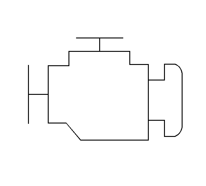
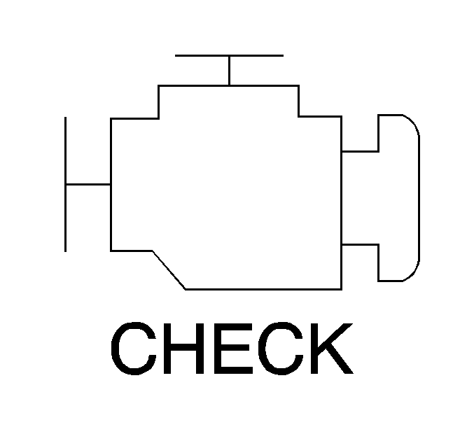
The malfunction indicator lamp (MIL) is located in the instrument panel cluster. The MIL will display as either SERVICE ENGINE SOON or one of the following symbols when commanded ON:


The MIL indicates that an emissions related fault has occurred and vehicle service is required.
The following is a list of the modes of operation for the MIL:
| • | The MIL illuminates when the ignition is turned ON, with the engine OFF. This is a bulb test to ensure the MIL is able to illuminate. |
| • | The MIL turns OFF after the engine is started if a diagnostic fault is not present. |
| • | The MIL remains illuminated after the engine is started if the control module detects a fault. A diagnostic trouble code (DTC) is stored any time the control module illuminates the MIL due to an emissions related fault. The MIL turns OFF after three consecutive ignition cycles in which a Test Passed has been reported for the diagnostic test that originally caused the MIL to illuminate. |
| • | The MIL flashes if the control module detects a misfire condition which could damage the catalytic converter. |
| • | When the MIL is illuminated and the engine stalls, the MIL will remain illuminated as long as the ignition is ON. |
| • | When the MIL is not illuminated and the engine stalls, the MIL will not illuminate until the ignition is cycled OFF and then ON. |
Trip
A trip is an interval of time during which the diagnostic test runs. A trip may consist of only a key cycle to power up the powertrain control module (PCM), allow the diagnostic to run, then cycle the key off to power down the PCM. A trip may also involve a PCM power up, meeting specific conditions to run the diagnostic test, then powering down the PCM. The definition of a trip depends upon the diagnostic. Some diagnostic tests run only once per trip (i.e., catalyst monitor) while other tests run continuously during each trip (i.e., misfire).
Warm-Up Cycle
The powertrain control module (PCM) uses warm-up cycles to run some diagnostics and to clear any diagnostic trouble codes (DTCs). A warm-up cycle occurs when the engine coolant temperature increases 22°C (40°F) from the start-up temperature. The engine coolant must also achieve a minimum temperature of 71°C (160°F). The PCM counts the number of warm-up cycles in order to clear the malfunction indicator lamp (MIL). The PCM will clear the DTCs when 40 consecutive warm-up cycles occur without a malfunction.
Diagnostic Trouble Codes (DTCs)
The powertrain control module (PCM) is programmed with test routines that test the operation of the various systems the PCM controls. Some tests monitor internal PCM functions. Many tests are run continuously. Other tests run only under specific conditions, referred to as Conditions for Running the DTC. When the vehicle is operating within the conditions for running a particular test, the PCM monitors certain parameters and determines if the values are within an expected range. The parameters and values considered outside the range of normal operation are listed as Conditions for Setting the DTC. When the Conditions for Setting the DTC occur, the PCM executes the Action Taken When the DTC Sets. Some DTCs alert the driver via the malfunction indicator lamp (MIL) or a message. Other DTCs do not trigger a driver warning, but are stored in memory. The PCM also saves data and input parameters when most DTCs are set. This data is stored in the Freeze Frame and/or Failure Records.
The DTCs are categorized by type. The DTC type is determined by the MIL operation and the manner in which the fault data is stored when a particular DTC fails. In some cases there may be exceptions to this structure. Therefore, when diagnosing the system it is important to read the Action Taken When the DTC Sets and the Conditions for Clearing the DTC in the supporting text .
There are different types of DTCs and different actions taken when the DTCs set. Refer to Diagnostic Trouble Code (DTC) Type Definitions for a description of the general characteristics of each DTC type.
DTC Status
When the scan tool displays a DTC, the status of the DTC is also displayed. The following DTC statuses are indicated only when they apply to the DTC that is set.
Fail This Ign. (Fail This Ignition): Indicates that this DTC failed during the present ignition cycle.Last Test Fail: Indicates that this DTC failed the last time the test ran.
MIL Request: Indicates that this DTC is currently requesting the malfunction indicator lamp (MIL). This selection will report type B DTCs only when they have requested the MIL (failed twice).
Test Fail SCC (Test Failed Since Code Clear): Indicates that this DTC that has reported a failure since the last time DTCs were cleared.
History: Indicates that the DTC is stored in the powertrain control module (PCM) History memory. Type B DTCs will not appear in History until they have requested the MIL (failed twice). History will be displayed for all type A DTCs and type B DTCs (which have requested the MIL) that have failed within the last 40 warm-up cycles. Type C DTCs that have failed within the last 40 warm-up cycles will also appear in History.
Not Run SCC (Not Run Since Code Clear): DTCs will be listed in this category if the diagnostic has not run since DTCs were last cleared. This status is not included with the DTC display since the DTC can not be set if the diagnostic has not run. This information is displayed when DTC Info is requested using the scan tool.