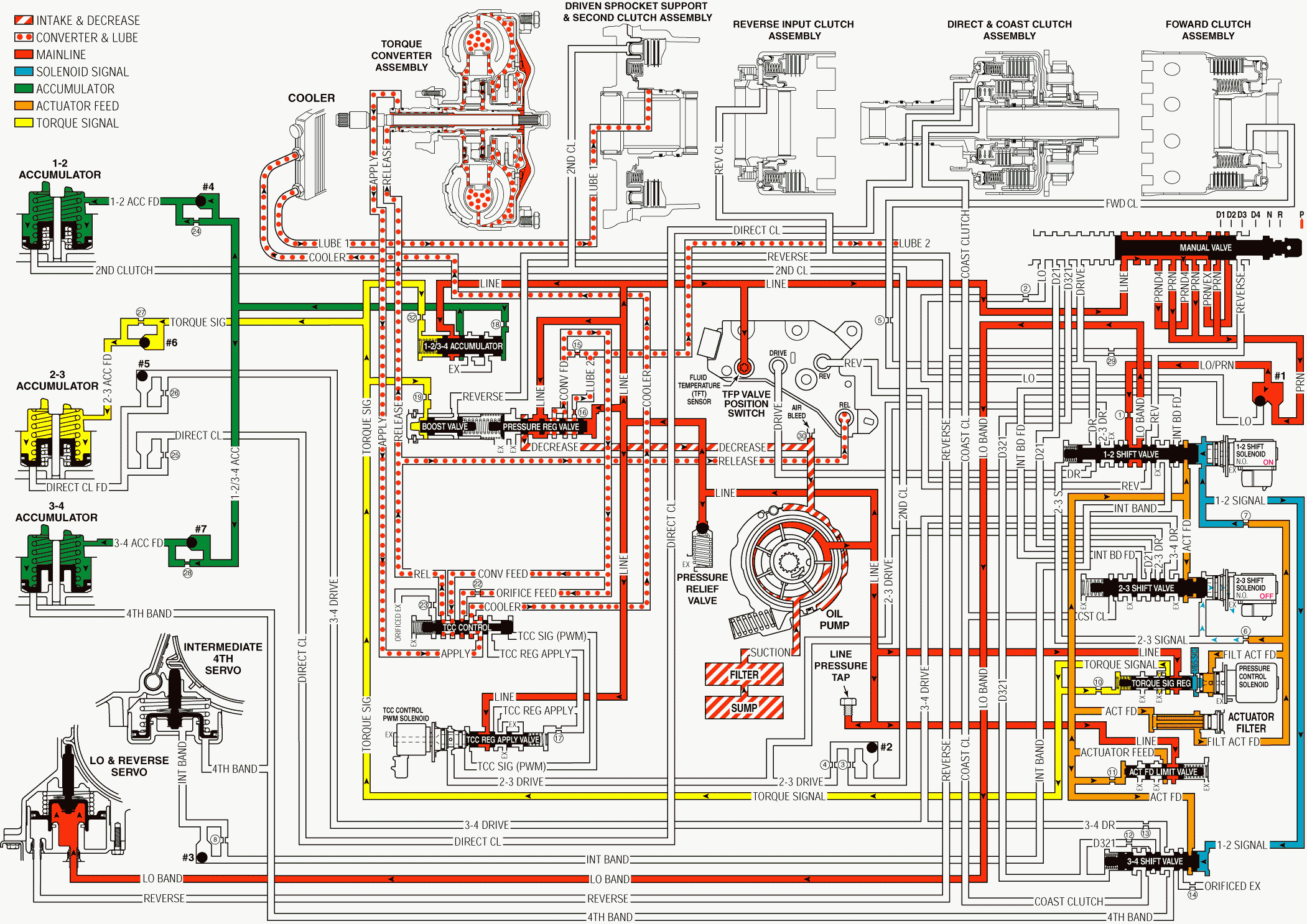
Park or Neutral - Engine Running W/O Electronic Range Select Mode
When the gear selector lever is in the Park (P) position and the engine is running, fluid is drawn into the oil pump. Line pressure is directed to the pressure regulator valve.
Pressure Regulation
Pressure Regulator Valve
The pressure regulator valve regulates the pump output (line pressure) in response to a torque signal fluid pressure, which acts on the boost valve, the spring force, and the line pressure acting on the end of the valve. Line pressure is directed to the manual valve, to both accumulator valves, to the torque signal regulator valve, to the TCC regulated apply valve, to the temperature sensor in the Automatic Transmission Fluid Pressure Manual Valve Position Switch (TFP Val. Position Sw.), and to the actuator feed limit valve. Also, line pressure feeds the converter feed fluid circuit through the pressure regulator valve.
Actuator Feed Limit (AFL) Valve
Line pressure is routed through the valve and into the actuator feed fluid circuit. The valve limits the actuator feed fluid pressure to a maximum pressure. Actuator feed fluid is routed to the pressure control solenoid and to each of the shift valves. The fluid also feeds the 1-2 signal and the 2-3 signal fluid circuits.
Pressure Control Solenoid (PCS) Valve
Controlled by the PCM, the PCS valve regulates the filtered actuator feed fluid pressure which acts on the end of the torque signal regulating valve.
Torque Signal Regulating Valve
Important: Actuator feed fluid continues to feed the 2-3 signal fluid circuit through orifice #6. However, the exhaust port through the 2-3 shift solenoid valve is larger that orifice #6 in order to prevent a pressure increase in the 2-3 signal fluid circuit.
The torque signal regulating valve regulates the line pressure into the torque signal fluid circuit. Filtered actuator feed fluid pressure from the PCS controls this regulation. torque signal fluid pressure is routed to the accumulator valves and to the boost valve in order to control shift feel.
Low and Reverse Band Applies
Manual Valve
The gear selector lever mechanically controls the manual valve, which is in Park (P) position. The manual valve directs line pressure into the PRND4 and the PRN fluid circuits.
Automatic Transmission Fluid Pressure Manual Valve Position Switch (TFP Val. Position Sw.) Assembly
PRND4 fluid is routed to the PRND4 fluid pressure switch in the TFP Val. Position Sw. Assembly, which signals the PCM that the transmission is in the Park (P) position. Line pressure is routed to the A/T Fluid Temperature Sensor in the TFP Val. Position Sw. Assembly.
1-2 Shift Solenoid Valve
Energized by the PCM, the normally open 1-2 shift solenoid valve is On and blocks the 1-2 signal fluid from exhausting. The 1-2 signal fluid pressure acts on the 1-2 and the 3-4 shift valves.
1-2 Shift Valve
The 1-2 signal fluid pressure holds the valve in the downshifted position against a spring force. Low/PRN fluid is routed through the 1-2 shift valve and into the Low band fluid circuit.
Low and Reverse Servo
Low band fluid is routed to the inner area of the servo piston. Low band fluid pressure moves the servo piston and pin assembly against a spring force in order to apply the low/reverse band.
2-3 Shift Solenoid Valve
The normally open 2-3 shift solenoid is Off and the 2-3 signal fluid is exhausted through the solenoid.
2-3 Shift Valve
A spring force holds the 2-3 shift valve in the downshifted position.
3-4 Shift Valve
The 1-2 signal fluid pressure holds the 3-4 shift valve against a spring force in the First and the Fourth gear positions.
Lube 2
The lube 2 fluid circuit is fed by line pressure at the pressure regulator valve. Lube 2 fluid is routed through the oil feed pipes and into the forward clutch support. Lube 2 fluid provides lubrication in the rear of the transmission.
Shift Accumulation
1-2/3-4 Accumulator Valves
Line pressure is regulated into accumulator fluid pressure. Torque signal fluid pressure acting on the end of the valve basically controls this regulation.
1-2, and 3-4 Accumulator Assemblies
Accumulator fluid is routed to each of the accumulator assemblies in preparation for upshifts. The fluid which is routed to the 1-2 and to the 3-4 accumulators is orificed by the #4 and the #7 checkballs. The 2-3 accumulator fluid circuit does not use a checkball in order to orifice accumulator fluid to the 2-3 accumulator.
Torque Converter/Cooler and Lube Circuits
Refer to reverse range for a complete description of these circuits.
Park - Engine Running - Without Electronic Range Select Mode

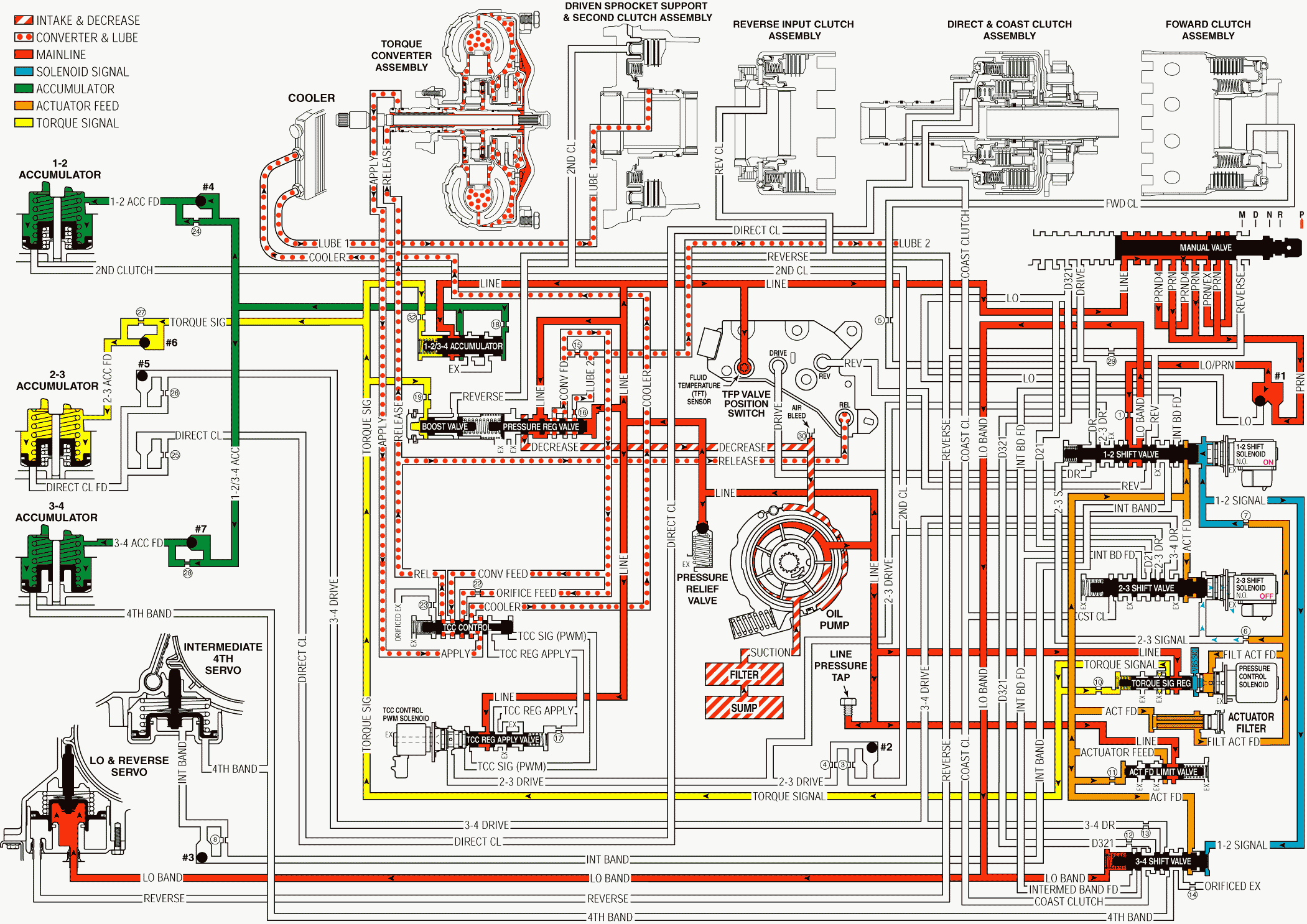
Park or Neutral - Engine Running With Electronic Range Select Mode
When the gear selector lever is in the Park (P) position and the engine is running, fluid is drawn into the oil pump. Line pressure is directed to the pressure regulator valve.
Pressure Regulation
Pressure Regulator Valve
The pressure regulator valve regulates the pump output (line pressure) in response to a torque signal fluid pressure, which acts on the boost valve, the spring force, and the line pressure acting on the end of the valve. Line pressure is directed to the manual valve, to both accumulator valves, to the torque signal regulator valve, to the TCC regulated apply valve, to the temperature sensor in the Automatic Transmission Fluid Pressure Manual Valve Position Switch (TFP Val. Position Sw.), and to the actuator feed limit valve. Also, line pressure feeds the converter feed fluid circuit through the pressure regulator valve.
Actuator Feed Limit (AFL) Valve
Line pressure is routed through the valve and into the actuator feed fluid circuit. The valve limits the actuator feed fluid pressure to a maximum pressure. Actuator feed fluid is routed to the pressure control solenoid and to each of the shift valves. The fluid also feeds the 1-2 signal and the 2-3 signal fluid circuits.
Pressure Control Solenoid (PCS) Valve
Controlled by the PCM, the PCS valve regulates the filtered actuator feed fluid pressure which acts on the end of the torque signal regulating valve.
Torque Signal Regulating Valve
Important: Actuator feed fluid continues to feed the 2-3 signal fluid circuit through orifice #6. However, the exhaust port through the 2-3 shift solenoid valve is larger that orifice #6 in order to prevent a pressure increase in the 2-3 signal fluid circuit.
The torque signal regulating valve regulates the line pressure into the torque signal fluid circuit. Filtered actuator feed fluid pressure from the PCS controls this regulation. torque signal fluid pressure is routed to the accumulator valves and to the boost valve in order to control shift feel.
Low and Reverse Band Applies
Manual Valve
The gear selector lever mechanically controls the manual valve, which is in Park (P) position. The manual valve directs line pressure into the PRND4 and the PRN fluid circuits.
Automatic Transmission Fluid Pressure Manual Valve Position Switch (TFP Val. Position Sw.) Assembly
PRND4 fluid is routed to the PRND4 fluid pressure switch in the TFP Val. Position Sw. Assembly, which signals the PCM that the transmission is in the Park (P) position. Line pressure is routed to the A/T Fluid Temperature Sensor in the TFP Val. Position Sw. Assembly.
1-2 Shift Solenoid Valve
Energized by the PCM, the normally open 1-2 shift solenoid valve is On and blocks the 1-2 signal fluid from exhausting. The 1-2 signal fluid pressure acts on the 1-2 and the 3-4 shift valves.
1-2 Shift Valve
The 1-2 signal fluid pressure holds the valve in the downshifted position against a spring force. Low/PRN fluid is routed through the 1-2 shift valve and into the Low band fluid circuit.
Low and Reverse Servo
Low band fluid is routed to the inner area of the servo piston. Low band fluid pressure moves the servo piston and pin assembly against a spring force in order to apply the low/reverse band. The low band fluid is routed to the 3-4 shift valve. The pressure moves the valve against 1-2 signal fluid.
2-3 Shift Solenoid Valve
The normally open 2-3 shift solenoid is Off and the 2-3 signal fluid is exhausted through the solenoid.
2-3 Shift Valve
A spring force holds the 2-3 shift valve in the downshifted position.
3-4 Shift Valve
The 1-2 signal fluid pressure holds the 3-4 shift valve against a spring force in the First and the Fourth gear positions.
Lube 2
The lube 2 fluid circuit is fed by line pressure at the pressure regulator valve. Lube 2 fluid is routed through the oil feed pipes and into the forward clutch support. Lube 2 fluid provides lubrication in the rear of the transmission.
Shift Accumulation
1-2/3-4 Accumulator Valves
Line pressure is regulated into accumulator fluid pressure. Torque signal fluid pressure acting on the end of the valve basically controls this regulation.
1-2, and 3-4 Accumulator Assemblies
Accumulator fluid is routed to each of the accumulator assemblies in preparation for upshifts. The fluid which is routed to the 1-2 and to the 3-4 accumulators is orificed by the #4 and the #7 checkballs. The 2-3 accumulator fluid circuit does not use a checkball in order to orifice accumulator fluid to the 2-3 accumulator.
Torque Converter/Cooler and Lube Circuits
Refer to reverse range for a complete description of these circuits.
Park - Engine Running - With Electronic Range Select Mode

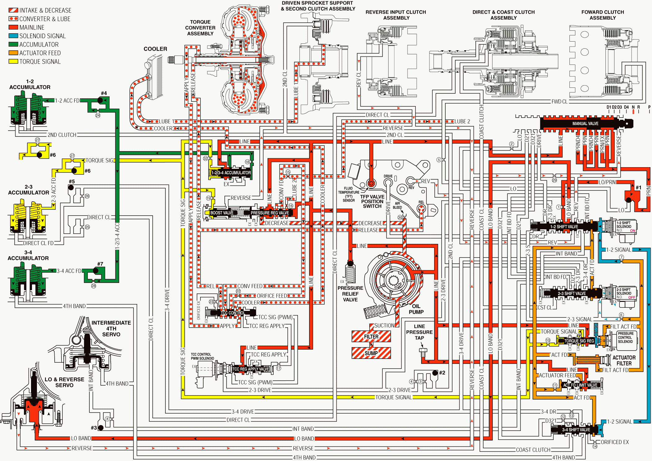
Park or Neutral - Engine Running W/O Electronic Range Select Mode
When you move the gear selector lever from the Reverse position to the Neutral position, the following changes occur to the hydraulic and electrical systems.
Reverse Clutch Releases
Manual Valve
The manual valve is moved to the Neutral position, where the valve blocks the line pressure from entering the Reverse fluid circuit. The reverse fluid circuit is opened to an exhaust at the manual valve.
Reverse Clutch
Reverse fluid exhausts from the reverse clutch and the clutch releases. This action shifts the transmission in to Neutral position.
Boost Valve
Reverse fluid exhausts from the boost valve and line pressure regulation returns to the normal operating range.
A/T Fluid Pressure Manual Valve Position Switch (TFP Val. Position Sw.) Assembly
Reverse fluid pressure exhausts from the TFP Val. Position Sw. Assembly. This action signals the PCM that the transmission is either in Neutral (N) or Park (P) position.
Low and Reverse Band Remains Applied
Important: In Park, Reverse, and Neutral positions the shift solenoid valves are shown to be in the First gear state. this is the normal operating state when the vehicle is stationary or at low vehicle speeds. However, the PCM will change the shift solenoid valve states depending on the speed of the vehicle. For example, if the Neutral range is selected when the vehicle is operating in Second gear, the shift solenoid valves will remain in a Second gear state. But with the manual valve in Neutral, line pressure is blocked, drive fluid exhausts and the transmission will shift into Neutral.
1-2 Shift Solenoid Valve
As in Park and Reverse positions, the solenoid valve is energized and 1-2 signal fluid pressure acts on the 1-2 shift valve.
1-2 Shift Valve
The 1-2 signal fluid pressure keeps the 1-2 shift valve in the downshifted position. Low/PRN fluid continues to feed the low band fluid circuit.
Low and Reverse Servo
Reverse fluid exhausts from the servo. However, low band fluid pressure continues to act on the inner area of the servo piston in order to keep the band applied.
Neutral - Engine Running - Without Electronic Range Select Mode

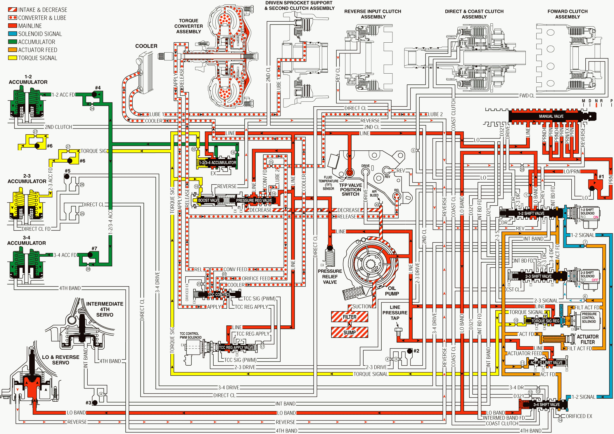
Park or Neutral - Engine Running With Electronic Range Select Mode
When you move the gear selector lever from the Reverse position to the Neutral position, the following changes occur to the hydraulic and electrical systems.
Reverse Clutch Releases
Manual Valve
The manual valve is moved to the Neutral position, where the valve blocks the line pressure from entering the Reverse fluid circuit. The reverse fluid circuit is opened to an exhaust at the manual valve.
Reverse Clutch
Reverse fluid exhausts from the reverse clutch and the clutch releases. This action shifts the transmission in to Neutral position.
Boost Valve
Reverse fluid exhausts from the boost valve and line pressure regulation returns to the normal operating range.
A/T Fluid Pressure Manual Valve Position Switch (TFP Val. Position Sw.) Assembly
Reverse fluid pressure exhausts from the TFP Val. Position Sw. Assembly. This action signals the PCM that the transmission is either in Neutral (N) or Park (P) position.
Low and Reverse Band Remains Applied
Important: In Park, Reverse, and Neutral positions the shift solenoid valves are shown to be in the First gear state. this is the normal operating state when the vehicle is stationary or at low vehicle speeds. However, the PCM will change the shift solenoid valve states depending on the speed of the vehicle. For example, if the Neutral range is selected when the vehicle is operating in Second gear, the shift solenoid valves will remain in a Second gear state. But with the manual valve in Neutral, line pressure is blocked, drive fluid exhausts and the transmission will shift into Neutral.
1-2 Shift Solenoid Valve
As in Park and Reverse positions, the solenoid valve is energized and 1-2 signal fluid pressure acts on the 1-2 shift valve.
1-2 Shift Valve
The 1-2 signal fluid pressure keeps the 1-2 shift valve in the downshifted position. Low/PRN fluid continues to feed the low band fluid circuit.
Low and Reverse Servo
Reverse fluid exhausts from the servo. However, low band fluid pressure continues to act on the inner area of the servo piston in order to keep the band applied.
Neutral - Engine Running - With Electronic Range Select Mode
