Circuit Description
The steering wheel position sensor (SWPS) provides one analog signal and 3 digital signals. The digital signals, Phase A, Phase B and marker pulse, are direct inputs to the rear wheel steering control module. The analog signal is input to the BCM and is sent via a class 2 message to the rear wheel steering control module. Battery voltage is supplied to the sensor from the cruise fuse to operate the digital portion of the sensor.
A 12-volt reference is provided by the rear wheel steering control module to the Phase A, Phase B, and marker pulse circuits of the SWPS. The module monitors each circuit as it is either remains high or is pulled low by the SWPS.
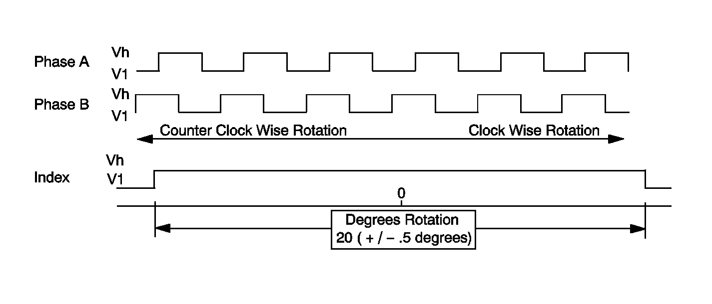
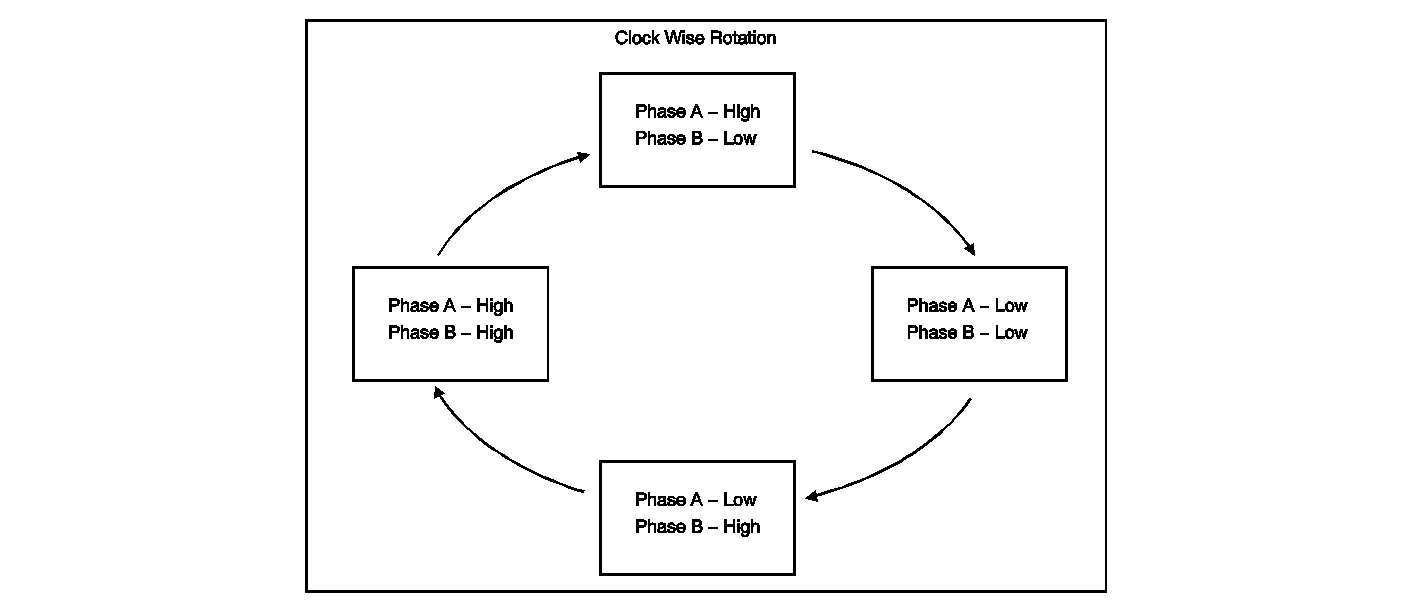
The scan tool displays the Phase A and Phase B data parameters as either HIGH or LOW when the steering wheel is being rotated. Each change from HIGH to LOW, or LOW to HIGH, represents one degree of steering wheel rotation. When observing the Phase A and Phase B data with the scan tool, the parameters will not always display the same value at the same time.
The marker pulse is a digital pulse signal that is displayed as HIGH by the scan tool with the steering wheel angle between +10 degrees and -10 degrees. At greater than 10 degrees steering wheel angle in either direction, the marker pulse data will be displayed as LOW.
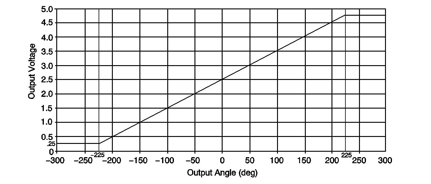
The BCM provides the 5-volt reference and low reference for the analog portion of the SWPS. The BCM reads the SWPS analog signal in voltage, which is typically 2.5-volt with the steering wheel on center. The voltage ranges from 0.25-volt at approximately 1 full turn left to 4.75-volt at approximately 1 full turn right. The voltage will then remain at that level for the remainder of steering wheel travel. This voltage can be monitored in BCM data display.
The rear wheel steering control module receives the analog signal via a class 2 message from the BCM. When monitoring the rear wheel steering data, this information is displayed in the Steering Wheel Angle (TBC) Data parameter, and is shown in degrees. The range of the display is +/- 225 degrees, with negative numbers representing steering input to the left, and positive numbers representing input to the right.
Conditions for running the DTC
Turn ON the ignition, with engine ON.
Conditions for Setting the DTC
| • | A condition that sets a BCM DTC C0472 or C0473 is present. |
| • | The marker pulse signal was low at less than +/-10 degrees of steering wheel angle and the steering wheel angle has changed more than 30 degrees. |
| • | The marker pulse signal was high at greater than +/-10 degrees of steering wheel angle and the steering wheel angle has changed more than 30 degrees. |
| • | No change in Phase A or Phase B signals and the steering wheel angle has changed more than 30 degrees. |
| • | The SWPS Phase A, Phase B, or marker pulse circuits have an open, short to ground, or short to battery voltage. |
Action Taken When the DTC Sets
| • | The Service 4-Wheel Steer indicator in IPC will be displayed. |
| • | The code is displayed on the scan tool as DTC C0455. |
| • | The output to the motor is ramped down slowly, at a rate of 2 degrees per second to 0 degrees and held. |
| • | The rear wheels will be returned to the centered position. |
| • | The internal power relay of the rear wheel steering control module is turned off, which in turn shuts down the 12-volt reference to the SWPS. This results in all digital signals being displayed as low by the scan tool. Battery voltage and hall sensor reference voltage will also display low voltage. This occurs only when the DTC is current. |
Conditions for Clearing the DTC
| • | Conditions for DTC are not currently present. |
| • | The module receives a clear code command from the scan tool. |
| • | The DTC clears after 100 malfunction free ignition cycles. |
Diagnostic Aids
Important: When the DTC is current, the internal power relay of the rear wheel steering control module is turned OFF, which in turn shuts down the 12-volt reference to the SWPS. This results in all digital signals being displayed as low by the scan tool. Battery voltage and hall sensor reference voltage will also display low voltage. Cycling the ignition will cause the DTC to become a history code. When the DTC is a history code, the power relay is ON with ignition ON, and the 12-volt reference is supplied to the SWPS. During diagnosis, any steps that require monitoring data must be performed when the code is not current. Monitoring data while the DTC is current will result in inaccurate data being displayed, and misdiagnosis will result.
The following conditions are possible causes:
| • | A class 2 communication problem with the TBC. |
| • | The steering wheel was rotated with the steering gear disconnected. |
| • | A malfunctioning steering wheel position sensor is present. |
| • | A steering wheel position sensor circuit is open. |
| • | A steering wheel position sensor circuit was shorted. |
Perform an inspection of the wiring and of the connectors. Failure to carefully inspect the wiring and the connectors may result in misdiagnosis. Misdiagnosis causes part replacement with reappearance of the malfunction.
Steering Wheel Position Sensor -- Digital Signal
| • | 3 outputs used (Phase A, Phase B, Index Pulse) |
| • | Phase A & Phase B |
| Offset PWM wave forms created when turning the wheel |
| • | Index pulse |
| Signal is present only when steering wheel is within 10 degrees either side of center |
Output is used to determine Direction of Rotation and Rate of Rotation
Steering Wheel Position Sensor--Digital Signal

Steering Wheel Position Sensor--A and B Phase

Steering Wheel Position Sensor - Analog Signal

Test Description
The numbers below refer to the step numbers on the diagnostic table.
-
This step will help determine if the fault is in the analog or the digital portion of the SWPS.
-
This step determines if the condition is currently present.
-
This step will help determine if a short to voltage exists in any of the digital circuits. A short to voltage in any of these circuits will cause all parameters to remain high.
-
This step checks for proper voltage to the phase A and Phase B circuits at the sensor and for proper operation of the sensor.
-
This step checks for proper voltage to the marker pulse circuit of the sensor and for proper operation of the sensor.
-
This step checks for proper operation of the sensor circuits by testing the sensors ability to switch a voltage signal between high and low.
Step | Action | Values | Yes | No |
|---|---|---|---|---|
Schematic Reference: Rear Wheel Steering Schematics Connector End View Reference: Rear Wheel Steering Connector End Views | ||||
1 | Did you perform the Diagnostic System Check - Rear Wheel Steering? | -- | Go to Step 2 | |
2 |
Does the information indicate the DTC C0455 is current? | -- | Go to Step 3 | Go to Step 4 |
With the scan tool, monitor the DTC information in the BCM. Does the information indicate a DTC C0472 or C0473 is present? | -- | Go to DTC C0472 or C0473 | Go to Step 4 | |
Does the DTC C0455 become current? | -- | Go to Step 5 | Go to Diagnostic Aids | |
5 |
Important: Rotating the steering wheel in excess of 30 degrees from center in either direction will result in DTC C0455 becoming current. This will result in inaccurate data being displayed and will cause misdiagnosis. If this occurs, you must repeat steps 1 through 4 of the following procedure before monitoring the data parameters.
Does the steering wheel angle value change? | -- | Go to Step 13 | Go to Step 6 |
|
Important: If DTC C0455 becomes current during this step, you must repeat steps 1 through 4 of Step 5 before monitoring the data parameters. Using the scan tool, monitor the Phase A, Phase B, and Marker Pulse Data parameters. Do all parameters remain HIGH at all times with steering input? | -- | Go to Step 8 | Go to Step 7 | |
7 |
Important: If DTC C0455 becomes current during this step, you must repeat steps 1 through 4 of Step 5 before monitoring the data parameters. Using the scan tool, monitor the Phase A and Phase B Data parameters. Does the Phase A or Phase B parameter remain HIGH at all times with steering input? | -- | Go to Step 11 | Go to Step 12 |
8 | Test the battery positive voltage circuit of the steering wheel position sensor (SWPS) for an open or short to ground. Refer to Circuit Testing and Wiring Repairs in Wiring Systems. Did you find and correct the condition? | -- | Go to Step 22 | Go to Step 9 |
9 | Test the ground circuit of the SWPS for an open or high resistance. Refer to Circuit Testing and Wiring Repairs in Wiring Systems. Did you find and correct the condition? | -- | Go to Step 22 | Go to Step 10 |
10 | Test the Phase A, Phase B, and marker pulse circuits for a short to voltage. Refer to Circuit Testing and Wiring Repairs in Wiring Systems. Did you find and correct the condition? | -- | Go to Step 22 | Go to Step 14 |
11 | Test the Phase A or Phase B circuit for an open circuit. Refer to Circuit Testing and Wiring Repairs in Wiring Systems. Did you find and correct a condition? | -- | Go to Step 22 | Go to Step 14 |
12 | Test the Phase A or Phase B circuit for a short to ground. Refer to Circuit Testing and Wiring Repairs in Wiring Systems. Did you find and correct the condition? | -- | Go to Step 22 | Go to Step 14 |
13 | Test the marker pulse circuit for an open or short to ground. Refer to Circuit Testing and Wiring Repairs in Wiring Systems. Did you find and correct the condition? | -- | Go to Step 22 | Go to Step 15 |
|
Important: If DTC C0455 becomes current during this step, you must repeat steps 1 through 4 of Step 5 before performing the following test. With the ignition ON, use a DVOM to measure the voltage of the Phase A and Phase B circuits by back probing the circuits at the SWPS while slowly rotating the steering wheel back an forth over center. Does the voltage switch in the range specified? | 0.080-0.180 V to 10.5-12.0 V | Go to Step 19 | Go to Step 16 | |
|
Important: If DTC C0455 becomes current during this step, you must repeat steps 1 through 4 of Step 5 before performing the following test. With the ignition ON, use a DVOM to measure the voltage of the marker pulse circuit by back probing the circuit at the SWPS while rotating the steering wheel from center to more than 10 degrees but less than 30 degrees. Does the voltage change from high on center to low at greater than 10 degrees rotation? | 10.5-12.0 V to 0.080-0.180 V | Go to Step 19 | Go to Step 16 | |
16 | Does the voltage of a circuit tested in a previous step remain high at all times? | -- | Go to Step 18 | Go to Step 17 |
Does the voltage switch between high and low? | -- | Go to Step 19 | Go to Step 18 | |
18 | Inspect for poor connections at the SWPS. Refer to Testing for Intermittent Conditions and Poor Connections and Connector Repairs in Wiring Systems. Did you find and correct the condition? | -- | Go to Step 22 | Go to Step 20 |
19 | Inspect for poor connections at the rear wheel steering control module. Refer to Testing for Intermittent Conditions and Poor Connections and Connector Repairs in Wiring Systems. Did you find and correct the condition? | -- | Go to Step 22 | Go to Step 21 |
20 |
Important: Perform the learn alignment procedure. Refer to Wheel Alignment Measurement in Wheel Alignment. Replace the SWPS. Refer to Steering Wheel Position Sensor or Steering Shaft Lower Bearing Replacement in Steering Wheel and Column. Did you complete the replacement? | -- | Go to Step 22 | -- |
21 |
Important: Perform the learn alignment procedure. Refer to Wheel Alignment Measurement . Replace the rear wheel steering control module. Refer to Rear Wheel Steering Control Module Replacement . Did you complete the replacement? | -- | Go to Step 22 | -- |
22 |
Does the DTC reset? | -- | Go to Step 2 | System OK |